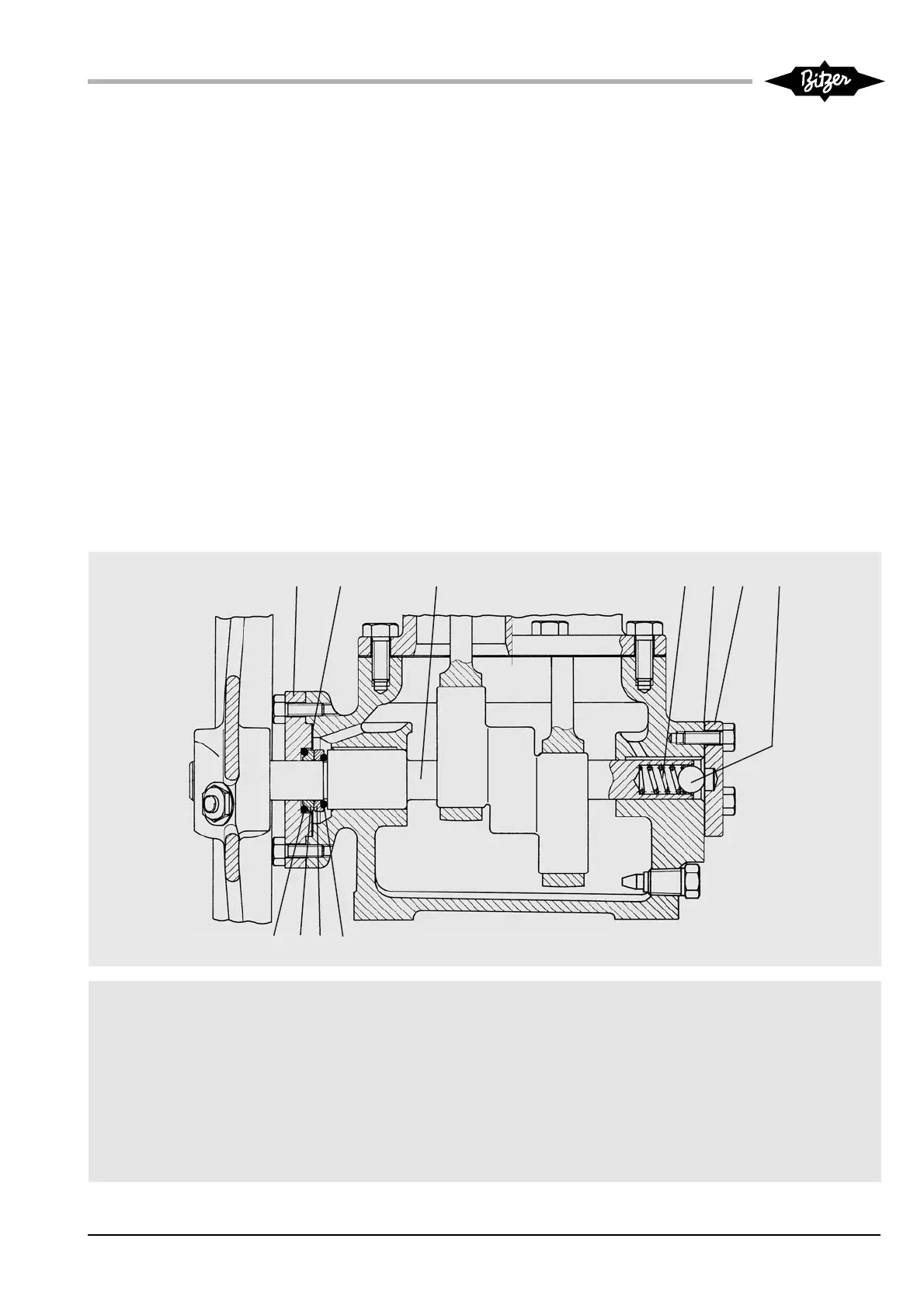
Abb. 5 Wellenabdichtung Fig. 5 Shaft seal
Fig. 5 Garniture d'étanchéité
1 Seitendeckel Side cover Couvercle latéral
2 Dichtung Gasket Joint
3 Welle Shaft Arbre
4 Feder Spring Ressort
5 Dichtung Gasket Joint
6 Abschlussdeckel End cover Couvercle de fermeture
7 Kugel Ball Boule
8 O-Ring O-ring Joint annulaire
9 Rotierender Gleitring Rotanting sealing cover Bague de glissement tournante
10 Statischer Gleitring Stationary sealing cover Bague de glissement statique
11 O-Ring O-ring Joint annulaire
1011 89
12 3
5467
21KB-510-4
• Place the new larger O-ring (11)
and the stationary sealing ring (10)
into the notch of the side cover (1).
• Place the new gasket (2) into the
housing flange. Fit the side co -
ver (1). Screw in the bolts squarely
and tighten them uniformly.
• Place the ball (7). Place the new
gasket (5) into the housing flange.
Fit the end cover (6) and retighten
it whilst turning the shaft. Screw in
the bolts squarely and tighten them
uniformly.
• Assemble flywheel according to
chapter 3.4.
• Open the shut-off valves of the
compressor.
• Repousser l'arbre vers l'intérieur en le
tournant.
• Mettre le plus grand joint annulaire(11)
et la bague de glissement statique
dans l'évidement du couvercle laté-
ral (1). Mettre le joint nouveau (2) dans
le flasque du carter. Mettre le cou-
vercle latéral. Serrer les vis uniformé-
ment et en croix.
• Remplacer la boule (7). Mettre le joint
nouveau (5) dans le flasque du carter.
Mettre le couvercle de fermeture (6) et
le refixer tout en tournant l'arbre.
Serrer les vis uniformément et en
croix.
• Monter le volant suivant chapitre 3.4.
• Ouvrir les vannes d'arrêt du compres-
seur.
• Welle unter Drehen nach innen
schieben.
• Neuen (größeren) O-Ring (11) und
statischen Gleitring (10) in die Aus -
spa rung des Seitendeckels (1) ein-
legen.
• Neue Dichtung (2) in Ge häuse -
flansch einsetzen. Seitendek kel (1)
aufsetzen. Schrauben über Kreuz
gleichmäßig anziehen.
• Kugel (7) einlegen. Neue Dich -
tung (5) in Ge häuse flansch einset-
zen. Abschlussdeckel (6) aufsetzen
und unter Drehen der Welle wieder
festziehen. Schrauben über Kreuz
gleichmäßig anziehen.
• Schwungrad montieren entspre-
chend Kapitel 3.4.
• Absperrventile des Verdichters öff-
nen.