19
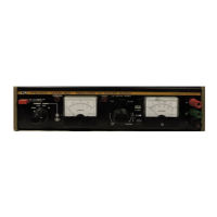
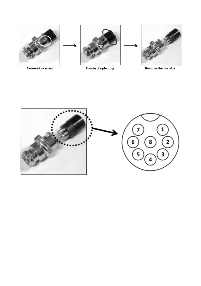
Figure 4 - Remote Control Connector
(b) Solder 5 wires (22AWG) to pins 1, 2, 3, 4, and 5 of pin plug. Refer to Figure 5
for pin numbers.
Figure 5 - Pin Numbers
(c) Make sure the load is disconnected and the power supply is OFF.
(d) Plug the remote connector plug into the analog remote control terminal of the
power supply.
(e) Secure the remote connector plug to the terminal socket by screwing in the
connector ring (Figure 6).