26
3.6.1 Connections
Assuming the multimeter is under factory default conditions, the basic procedure to measure continuity
is as follows:
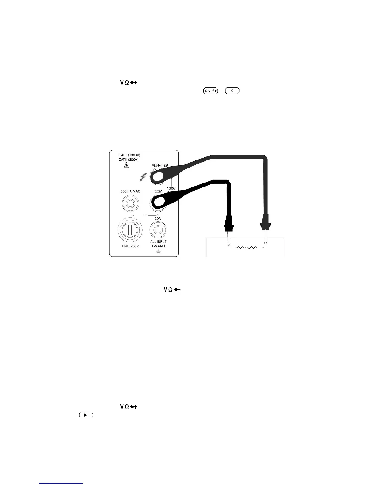
1. Connect test leads to and COM terminals.
2. Select Continuity measurement function by pressing → .
3. Connect test leads to the resistance under test as shown in Figure 3-5.
4. Take reading from the display
Figure 3-5 Continuity Measurement
Note: Source current flows from the to COM terminals.
3.7 Testing Diode
The multimeter can also be used to measure the forward voltage drop of general-purpose diodes and
zener diodes. A current range of 0.5 mA will be selected for diode measurement.
Note: Diode test uses medium reading rate and is fixed.
3.7.1 Connections
Assuming the multimeter is under factory default conditions, the basic procedure to test a diode is as
follows:
1. Connect test leads to and COM terminals.
2. Press for diode measurement function.
3. Connect test leads to the diode under test as shown in Figure 3-6.
4. Take a reading from the display.