7
1. 8 7 7. 8 7 7. 2 2 6 9 BLACKBOX.COM
NEED HELP?
LEAVE THE TECH TO US
LIVE 24/7
TECHNICAL
SUPPORT
1.8 7 7. 87 7. 2269
CHAPTER 2: OVERVIEW
2.4 HARDWARE DESCRIPTION
2.4.1 TRANSMITTER
FRONT PANEL
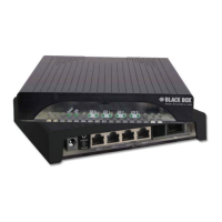
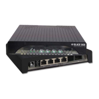
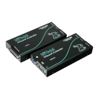
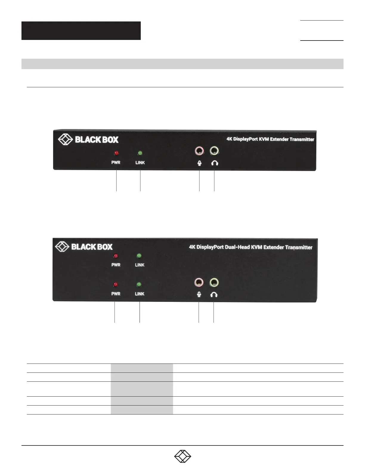
Figure 2-1 shows the front panel that is common the single-head CATx and the fiber transmitters. Table 2-1 describes the components.
1 2 3 4
FIGURE 2-1. SINGLE-HEAD TRANSMITTER FRONT PANEL
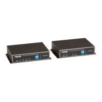
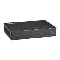
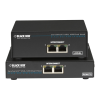
Figure 2-2 shows the front panel that is common to the dual-head CATx and fiber transmitters. Table 2-1 describes the components.
1 2 3 4
FIGURE 2-2. DUAL-HEAD TRANSMITTER FRONT PANEL
TABLE 2-1. TRANSMITTER FRONT-PANEL COMPONENTS
NUMBER IN FIGURE 2-1 OR 2-2 COMPONENT DESCRIPTION
1 PWR LED Lights when power to the transmitter is ON
2 Link LED
Lights when the link between transmitter and receiver units is ON;
OFF when the link between transmitter and receiver units is OFF
3 Audio jack Connects to analog audio input for audio extension
4 Audio jack Connects to analog audio output for audio extension
 Loading...