5
NEED HELP?
LEAVE THE TECH TO US
LIVE 24/7
TECHNICAL
SUPPORT
1.8 77. 877.2 269
1. 8 7 7. 8 7 7. 2 2 6 9 BLACKBOX.COM
CHAPTER 2: OVERVIEW
2.4 HARDWARE DESCRIPTION
2.4.1 L H C210A
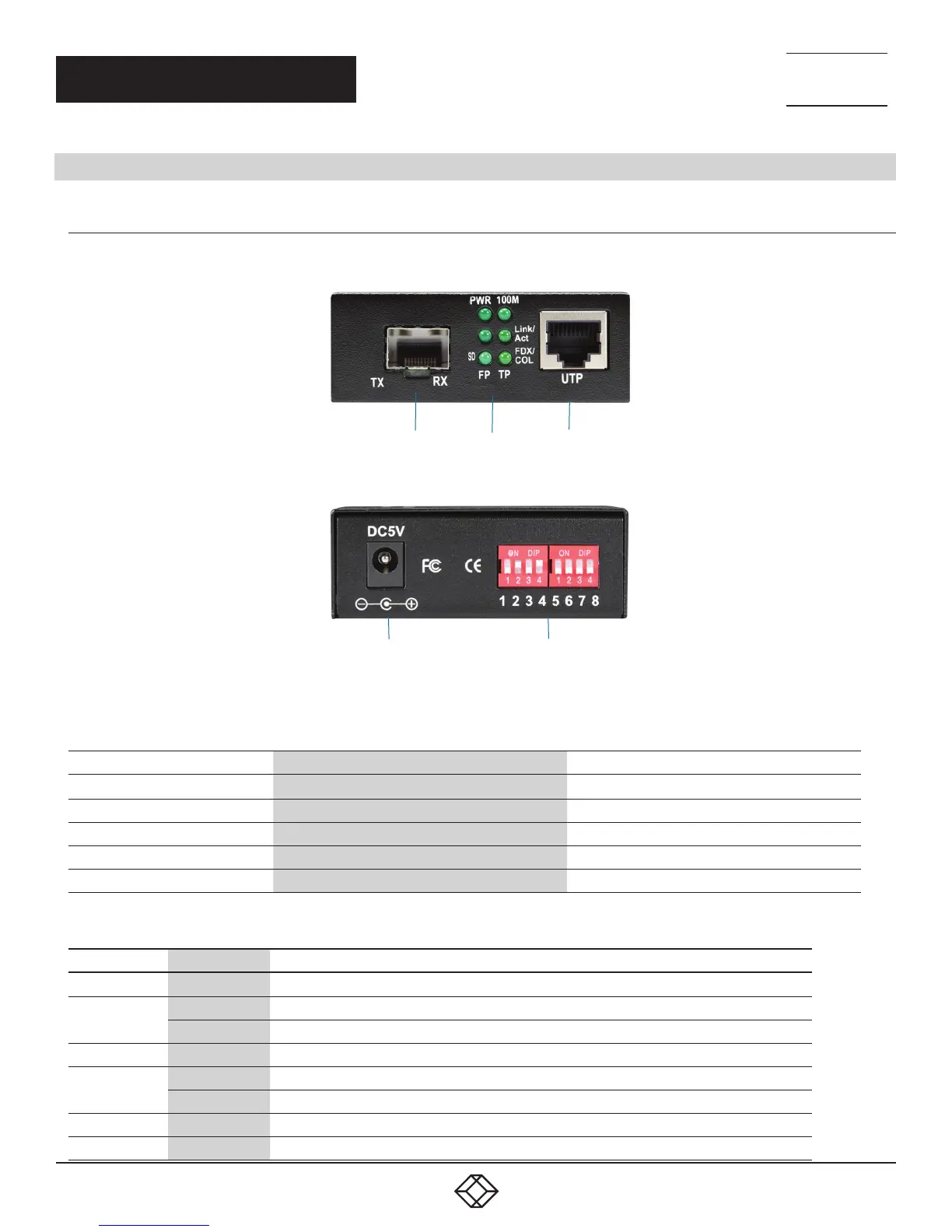
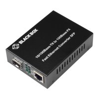
Figures 2-1 and 2-2 show the front and back panels of the LHC210A converter. Tables 2-1 and 2-2 describe its components.
1 2 3
FIGURE 2-1. LHC210A FRONT PANEL
4 5
FIGURE 2-2. LHC210A BACK PANEL
TABLE 2-1. LHC210A MEDIA CONVERTER COMPONENTS
NUMBER IN FIGURE 2-1 OR 2-2 COMPONENT DESCRIPTION
1 SFP cage SFP module installs here
2
LED indicators
See Table 2-2
3
RJ-45 connector
Links to RJ-45 cable
4
Barrel connector for power
Links to 47–57-VDC power supply
5
(2) 4-position DIP switches, numbered 1–8 See Table 3-2
TABLE 2-2. LHC210A LED INDICATORS
LED NAME STATUS DESCRIPTION
PWR ON Power is ON and normal
FX Link/ACT
ON
Connection Status display for fiber link. ON indicates that the fiber link is correctly connected
Blinking
Packet is being transmitted through the FX end
SD
ON
Fiber signal is detected
100M
ON
Link is operating at 100 Mbps
OFF Link is operating at 10 Mbps
TX Link/Act
ON
Connection status display for copper link. ON indicates that the link is correctly connected
TX FDX/COL
Blinking
Active status display of copper link. Packet is being transmitted through the TX end



 To Next Page