MATRIX. INSTRUCTION MANUAL
5
INSTALLING THE AILERON LINKAGES
1. Working with the aileron linkage for
now, thread one clevis onto one of the
threaded wires.
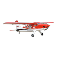
2. Attach the clevis to the outer hole in the
control horn. Install a silicone tube on the
clevis.
4. Locate one nylon servo arm, and using
wire cutters,remove all but one of the arms.
Using a 2mm drill bit, enlarge the third hole
out from the center of the arm to accommodate
the aileron pushrod wire.
3. Plug the aileron servo into the receiver
and center the servo. Install the servo arm onto
the servo. The servo arm should be
perpendicular to the servo and point toward
the middle of the wing.
5. Using pliers, carefully make a 90
degree bend down at the mark made. Cut off
the excess wire, leaving about 4mm beyond
the bend.
6. Insert the 90 degree bend down through
the hole in the servo arm. Install one nylon
snap keeper over the wire to secure it to the
arm. Install the servo arm retaining screw and
remove the masking tape from the aileron.
Repeat the procedure for the other wing
half.
JOINING THE WING HALVES
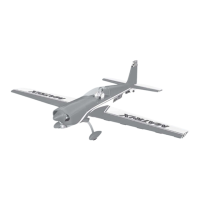
1. Locate the aluminium wing dihedral
brace.
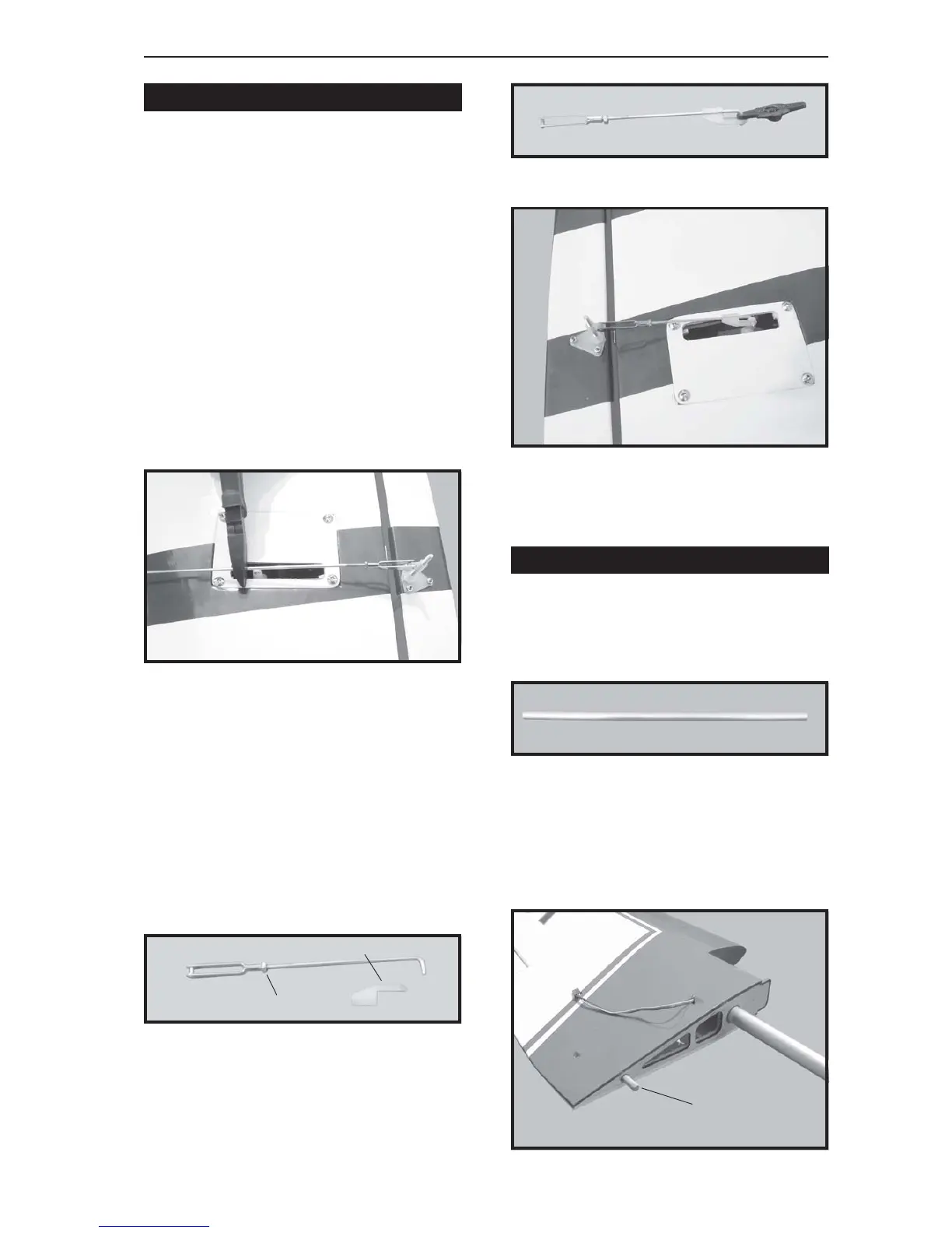
2. Test fit the dihedral brace into each
wing half. The brace should slide in easily . If
not, use 220 grit sandpaper with a sanding
block and sand down the edges and ends of
the brace until it fits properly.
M2 lock nut.
M2 clevis. Snap keeper.
Dowel
 Loading...