4646
Helm Control Systems
dicate that the control is activated and the engine
can be started.
The most common features activated or moni-
tored by the keypad are:
• Starter lockout, which prevents the engine from
being started in gear.
• Gear lockout, which allows the engine RPM to
be advanced in neutral safely.
• Battery voltage warning indicator that warns
the operator of high or low voltage supplied to
the system (audible alarm.)
• Trolling feature that allows the operator to in-
crease the engine speed in 50 RPM increments
while operating at trolling speeds between 600
- 1000 RPM.
These features and others not mentioned require
specic procedures to activate and operate them
properly. Some of the procedures and features are
unique to the engine and other options installed on
your boat. It is essential that you read the owner’s
manual for the controls and be completely familiar
with their operation before using your boat.
ALWAYS RETURN THE ENGINE THROTTLE LEVER TO THE
EXTREME LOW SPEED POSITION BEFORE SHIFTING. NEVER
SHIFT THE UNIT WHILE ENGINE SPEED IS ABOVE IDLE RPM.
Electronic Engine Controls - Twin Engines
Electronic engine controls are standard on some
engines and an available option on others. The
following description is typical of most electronic
control installations.
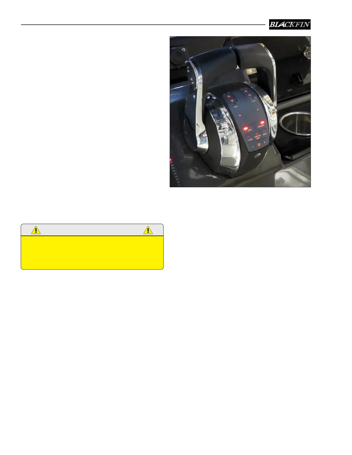
The helm is designed for a binnacle style control
with a single lever for each engine. The electronic
control system consists of three major compo-
nents: the electronic control head, instruments
and keypad, control processors and applicable
harnesses. The controls are completely electronic
and there are no cables.
The controls have a single lever for each engine
that operates as a gearshift and a throttle. Gen-
eral operation will include a position for neutral
(straight up and down or slightly aft of vertical),
a forward position (the 1st detent forward of neu-
Typical Mercury Twin Engine Electronic Controls
tral), and a reverse position (the 1st detent aft
of neutral). Advancing the control lever beyond
the shift range advances the throttle in forward or
reverse. Each control is equipped with a means of
permitting the engine to be operated at a higher
than idle RPM while in neutral for cold starting
and warm-up purposes. The control levers are
equipped with adjustable control head detent and
friction settings.
Most engine controls and key pads have inte-
grated switches and indicator lights which allow
the operator to control all aspects of the boat’s
propulsion system. LED lights on the control pad
indicate that the control is activated and the en-
gines can be started.
The most common features activated or
monitored by the keypad are:
• Starter lockout, which prevents the engine
from being started in gear.
• Gear lockout, which allows the engine RPM to
be advanced in neutral safely.
• Battery voltage warning indicator that warns
the operator of high or low voltage supplied
to the system (audible alarm.)
 Loading...