58
Electrical System
PROPER FUSE OR BREAKER PROTECTION MUST BE
PROVIDED FOR ALL 12 VOLT EQUIPMENT ADDED. DO
NOT OVERLOAD THE ACCESSORY CIRCUIT BREAKERS
OR OTHER CIRCUITRY THROUGH ADDITIONAL 12 VOLT
EQUIPMENT.
Battery Switch
The battery switch is located in a panel in the
head compartment. The switch is an OFF/1/2/1
& 2 (Both) battery selector switch identied by a
red knob.
An Automatic battery isolator/relay (DVSR) man-
ages the charging current for the engine and house
batteries. Whenever the engine is running, the
isolator/relay automatically senses the condition
of each battery and closes to direct the available
current to the battery that requires charging. The
engine starting and house batteries will continue
to be charged until the engine is shutdown and the
automatic relay opens, isolating the house battery
from the engine battery. The engine and house
batteries can be temporarily connected in parallel
by moving the switch to “1&2” position. This will
provide additional starting current for the engine.
When in port or at anchor, the engine battery
switch should be set to the 1 or 2 position. This
will keep one battery in reserve for starting the
engine. If the battery powering the house circuits
becomes discharged to the point that accessories
stop operating properly, the engine can be started
to recharge the battery by selecting the other
battery or setting the switch to position “1&2.”
Always turn the battery switch OFF when leaving
the boat unattended.
Notice:
Current is supplied to the automatic oat
switch for the bilge pump when the batter-
ies are connected and the battery switches
areo.
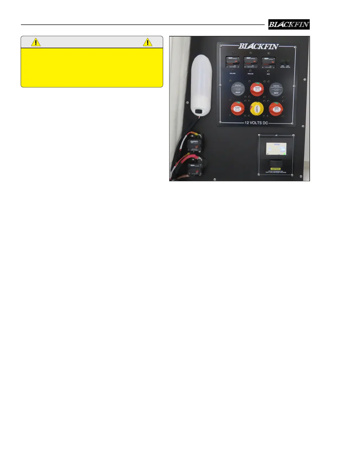
6.3 Twin Engine Battery System
The 12 volt system is a standard twin engine
marine system. There are three batteries located
in the head compartment, one for the starboard
engine, one for the port engine and one for the
house, accessory circuits and electronics. The bat-
teries themselves can be charged by the engines
or the optional battery charger, when hooked to
shore power.
Automatic battery isolator/relays (DVSR) manage
the charging current for the engine and house
batteries. The system is equipped with a battery
parallel feature that will connect both engine start-
ing batteries in parallel for extra battery power
while starting the engines.
Circuit Protection
Main breakers located near the battery switches
protect the main accessory circuit, stereo amplier
and optional windlass. Circuit breakers or fuses in
the panel or near the batteries protect the circuits
for the battery charger DC circuits, electronics
memory, and automatic switches for the bilge
pumps. Fuses located on each engine protect the
ignition, charging systems and gauges. Other
fuses or circuit breakers provided by the engine
manufacturer protect auxiliary charging circuits
and other engine related electronic controls.
Twin Engine Battery Switch Panel, Circuit Breakers,
Battery Switches & DVSR Relays


 To Next Page