________________________________________PL10C / PL20B_____________________________________
11
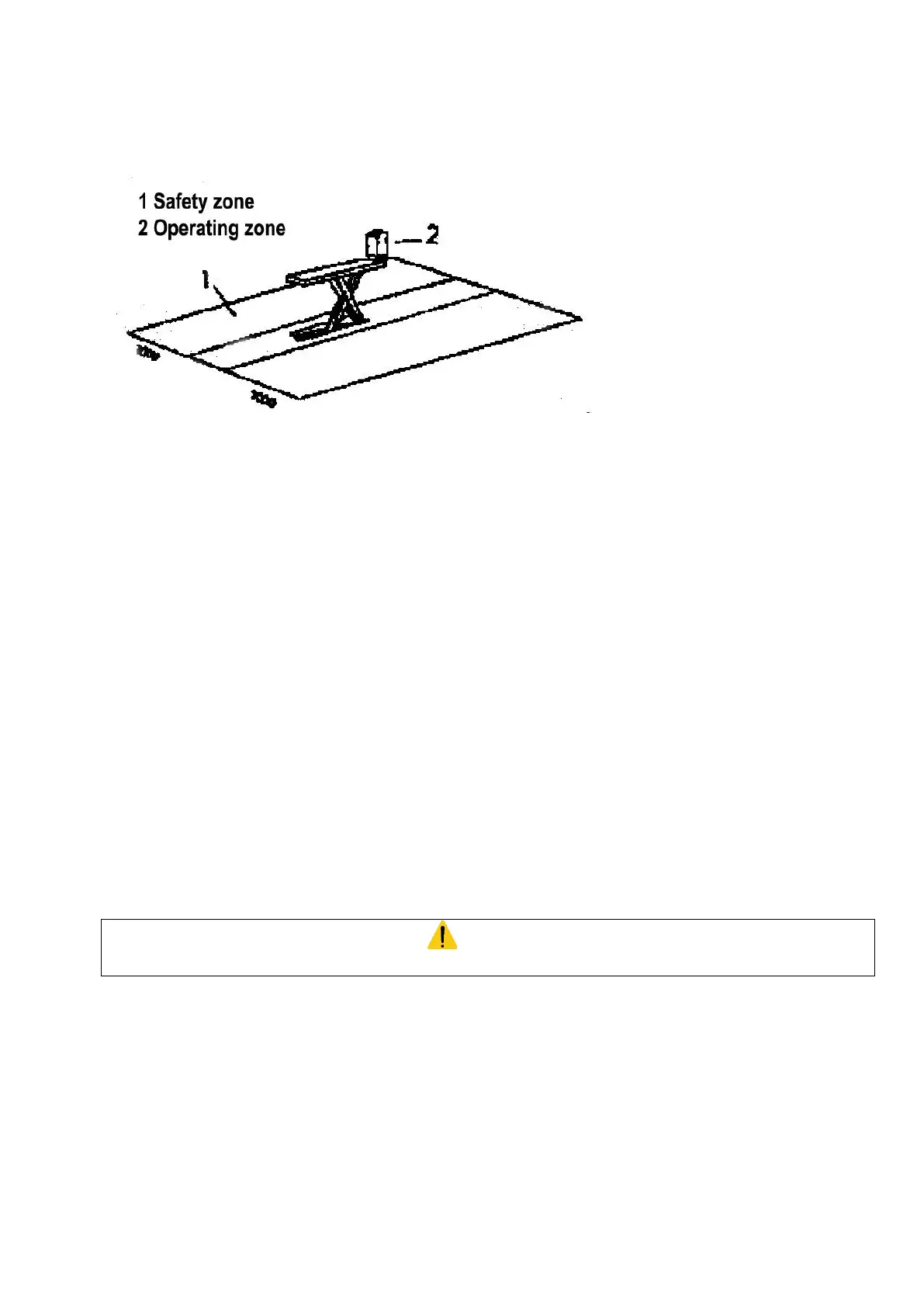
THE WEIGHT OF THE VEHICLE
The lift can be used with nearly any vehicle provided that the maximum loading capacity (2500 kg) is not exceeded.
The safety zone (Figure 13) is to some extent determined by the dimensions of the vehicle to be lifted.
Figure 13
VI) INSTALLATION
The lift must be installed taking into account the dimensions of the vehicles to be lifted.
The minimum distance from the walls should be 1900 mm for the PL10 version.
The minimum distance from the walls should be 750 mm (on the side) and 1900 mm (at the back) for the PL20.
- Sufficient room for operations
- Sufficient room to carry out maintenance, as well as space for access- and exit-routes.
- Position in relation to other machines
- The lift must be installed near a power supply point, to enable problem-free power connection.
LIFTING
The lifts must be adequately and uniformly lighted.
FLOOR
The lift must be installed on a flat, horizontal and sufficiently sturdy floor.
The concrete floor must have a minimum thickness of 150mm and a resistance of C20/25 (Norm EN206-1)
INSTALLATION IN A PIT
The lift must be installed following the instructions and civil engineering plans supplied by Blackhawk.
WARNING
No unauthorised person should be present during installation