3131
Using Videohub Routers
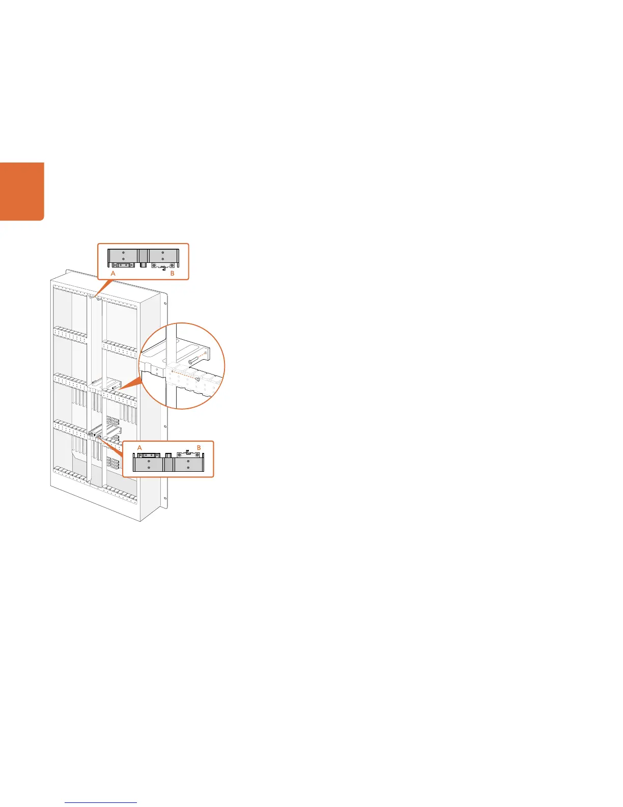
Step 8. Use a Torx T8 screwdriver to remove the silver catches from the two supporting bridges at the top
and bottom of the left crosspoint slot. In the accompanying illustration, the letter "A" indicates
the location on the left side of the supporting bridges where the silver catches have been
removed. When upgrading to a Universal Videohub 288 Crosspoint card at a later time, you will
need to reinstate the silver catches, so make sure you keep them in a safe place. The silver catches
shown at "B" should not be removed. They will be required if installing a Universal Videohub 288
Crosspoint card in the right crosspoint card slot in the future.
Step 9. To install the Universal Videohub 72 Crosspoint card, hold the card in a vertical orientation by
its two levers. The BNC, Ethernet and other ports should be towards the bottom end of the
card. Gently insert the unit into its slot, below the additional supporting bridge, and ensure the
top and bottom edges of the card follow the black guides. Now firmly push both levers flat to
fully engage the multi-pin connectors with the motherboard. Mating pins ensure that the card
precisely engages with the motherboard without damaging the multi-pin connectors. Use a
number 01 size Pozidriv screwdriver to secure the screws on the two levers of the crosspoint card.
Step 10. The short length of the Universal Videohub 72 Crosspoint card means that a short blanking plate
should also be installed to cover the rest of the long crosspoint slot. The short blanking plate can
be secured with a number 02 size Pozidriv screwdriver.
Step 11. Use a number 02 size Pozidriv screwdriver to reinstate the blanking plate for the right crosspoint
card slot.
Step 12. Reinstate the blanking plates for the interface card slots for SDI ports 73-216. Interface cards must
only be installed in the bottom row, for SDI ports 1-72, when a Universal Videohub 72 Crosspoint
card is used.