VALVE REPLACEMENT
CB9A-021 page 19/24
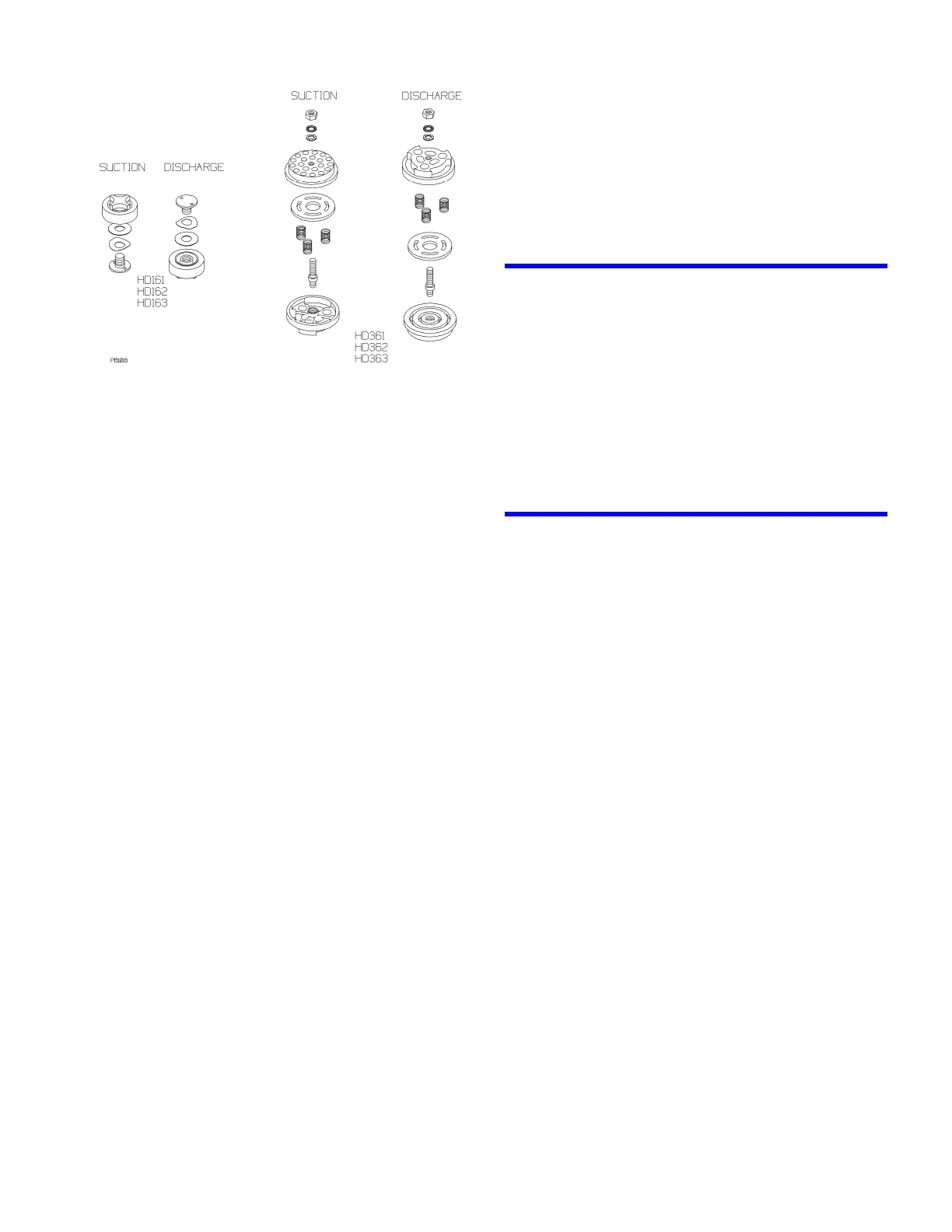
Fig. 12 – Typical Valve Assemblies
320, 340 and 360 Series Models:
a. Remove the valve cover plate capscrews then
lift off the cover plate and O-ring.
b. Remove the valve cage (and unloader
plunger).
c. Remove the valve assembly and valve gasket.
d. Inspect the valve for wear or breakage.
e. Valve Repair
i. Remove hex nut from valve (after
removing the unloader post retainer bolt,
actuator assembly, spring, and post.)
ii. Separate the valve halves and remove
springs and plate.
iii. Inspect and replace worn components.
iv. Reassemble valves as shown in the
drawing and tighten the valve assembly
nut or unloader post according to the Bolt
Torque Table.
v. (Reassemble the unloader spring, and
actuator then tighten the retainer bolt per
the Bolt Torque Table.)
4. To reinstall valves:
a. Install a new valve gasket into the cylinder
head (remove any old gaskets).
b. Install the valve assembly in the cylinder head.
Make sure the valve's orientation and location
are correct.
c. Center the valve cage on the valve assembly.
d. Applies only to suction valves with unloaders.
160 Series: Install unloader spring, actuator
and plunger in the cage.
320, 340 and 360 Series: Install the unloader
plunger in the cage.
e. 320, 340 and 360 Series Models:
Make sure the valve hold down screw is
removed from the cover plate, then install the
valve cover plate with a new O-ring. Tighten
the cover plate capscrews according to the
Bolt Torque Table.
f. Install the hold down screw and tighten
according to the Bolt Torque Table.
g. Install the valve cap (or unloader assembly)
and O-ring. (A little oil or grease on the O-ring
will help hold it in place during installation.)
5. After replacing the valves, rotate the flywheel by
hand to check for interference between the pistons
and the valves.
6. After 60 minutes of running time, remove the valve
cap (or unloader assembly) and retorque the hold
down screw. Replace the valve cap and O-ring.
UNLOADER SEAL REPLACEMENT
1. Remove the unloader cap and O-ring.
2. Remove the unloader body from the cylinder head
(a strap wrench is helpful).
3. Push the unloader piston out the top of the
unloader body.
4. Inspect and replace the seals as needed - note the
seal orientation!
5. Inspect the unloader body bore - it must be clean
and smooth.
6. Reassemble in the reverse order.
PISTON RING REPLACEMENT
1. Follow steps 1 through 3 of "Compressor
Disassembly."
2. Remove the piston rings and the piston ring
expanders from the pistons.
3. To replace the piston rings:
a. Place an expander in the top groove of the
piston. Place an expander in the second
groove with the break in this expander 180
degrees from the break of the top expander.
Place the third expander in the bottom groove
with its break in the same position as the top
expander.
b. Place piston rings in all three grooves of the
piston. Make sure the breaks in the piston
rings are directly opposite the breaks in the
corresponding expanders.
4. Reassemble the compressor per steps 10 through
14 of "Compressor Assembly."
 Loading...