101-B00 Page 4/16
COUPLING ALIGNMENT
The pump must be directly coupled to a gear and/or driver
with a flexible coupling. Verify coupling alignment after
installation of new or rebuilt pumps. Both angular and
parallel coupling alignment MUST be maintained between
the pump, gear, motor, etc. in accordance with
manufacturer’s instructions. See Figure 3.
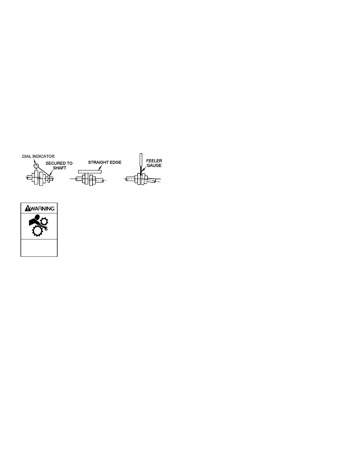
1. Parallel alignment: The use of a laser alignment tool or
dial indicator is preferred. If a laser alignment tool or dial
indicator is not available, use a straightedge. Turn both
shafts by hand, checking the reading through one
complete revolution. Maximum offset should be less
than .005" (.127 mm).
2. Angular alignment: Insert a feeler gauge between the
coupling halves. Check the spacing at 90° increments
around the coupling (four checkpoints). Maximum
variation should not exceed .005" (.127 mm). Some
laser alignment tools will check angular alignment as
well.
3. Replace the coupling guards after setting alignment.
Figure 3 – Alignment Check
Operation without guards in place can
cause serious personal injury, major
property damage, or death.
Do not operate
without guard
in place
GEAR REDUCER ALIGNMENT – GX MODELS
The reducer can be rotated on its mounting to raise or lower
the input shaft to facilitate alignment to the motor shaft. To do
so, first loosen the four clamp capscrews (20C) and the two
setscrews (33) in the gear reducer spool flange. The reducer
is then free to rotate. If necessary, tap it lightly with a soft
faced mallet. When aligning the reducer, verify the alignment
of the coupling halves as indicated in “Coupling Alignment”
section.
NOTICE:
To determine maximum variation of gear reducer shaft
alignment, refer to Blackmer GX model dimension pages
PUMP ROTATION
A right-hand pump rotates clockwise with the intake and relief
valve on the right side, when viewed from the driven end.
A left-hand pump rotates counterclockwise with the intake
and relief valve on the left side, when viewed from the driven
end.
NOTICE:
On GX models, the gear reducer input shaft will rotate in
the opposite direction of the pump shaft. For example,
on a right-hand GX pump, the gear reducer shaft will
rotate counterclockwise.
NOTICE:
Confirm correct pump rotation by checking the pump
rotation arrows respective to pump driver rotation.
TO CHANGE PUMP ROTATION
To reverse rotation, the pump must be disassembled then
reassembled with the shaft on the opposite side of the pump.
See the ‘Maintenance’ section for instructions.
CHECK VALVES
The use of check valves or foot valves in the supply tank is
not recommended with self-priming, positive displacement
pumps.
If the possibility of liquid backflow exists when the pump is
off, a check valve in the pump discharge piping is
recommended because the pump can motor in the reverse
rotation and create undue stress on all attached components.
Never start a pump when it is rotating in the reverse rotation
as the added starting torque can damage the pump and
related equipment.