101-B00 Page 8/16
VANE REPLACEMENT
NOTICE:
Maintenance shall be performed by qualified technicians
only. Follow the appropriate procedures and warnings
as presented in manual.
1. Flush the pump per instructions in this manual. Drain and
relieve pressure from the pump and system as required.
2. Remove the head assembly from the outboard
(nondriven) side of the pump according to steps 5 - 8 in
the "Pump Disassembly" section of this manual.
3. Turn the shaft by hand until a vane comes to the top (12
o'clock) position of the rotor. Remove the vane.
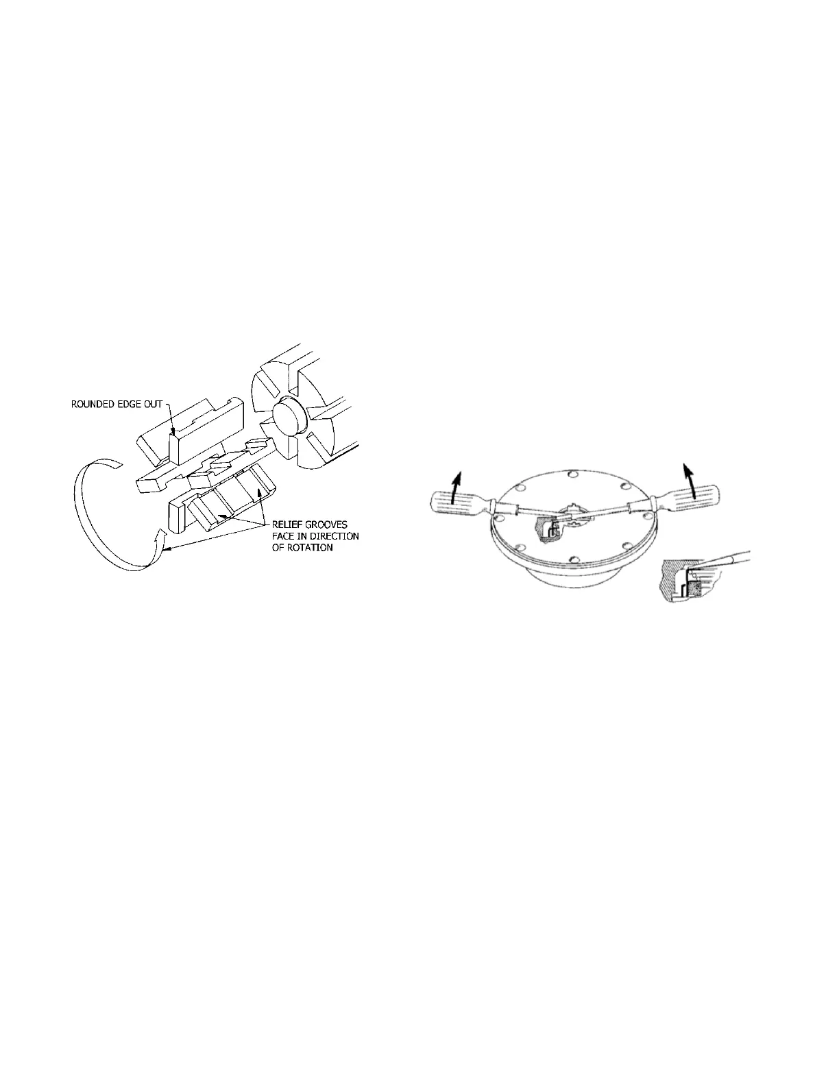
4. Install a new vane, ensuring that the rounded edge is UP,
and the relief grooves are facing towards the direction of
rotation. See Figure 4.
5. Repeat steps 3 and 4 until all vanes have been replaced.
6. Reassemble the pump according to the "Pump
Assembly." section of this manual.
Figure 4 – Vane Replacement
PUMP DISASSEMBLY
NOTICE:
Follow all hazard warnings and instructions provided in
the “Pump Maintenance” section of this manual.
1. Flush the pump per instructions in this manual. Drain and
relieve pressure from the pump and system as required.
2. On GX model pumps, disengage the motor shaft
coupling and remove the four clamp capscrews (20C) to
release the clamps (20B). Loosen the two setscrews (33)
in the gear reducer spool flange. The gear reducer can
then be rotated away from the motor shaft and lifted off
the pump. Refer to “Gear Reducer Maintenance” for
reducer disassembly instructions.
3. Starting on the inboard (driven) end of the pump, clean
the pump shaft thoroughly, making sure the shaft is free
of nicks and burrs. This will prevent damage to the
mechanical seal when the inboard head assembly is
removed.
4. On X/XH model pumps, remove the inboard bearing
cover capscrews (28) and slide the inboard bearing cover
(27A) and gasket (26) off the shaft. Discard the gasket.
On the X2 and X2.5-inch pump models, the dirt shield will
come off with the bearing cover. Inspect dirt shield and
replace as required.
5. Remove the outboard bearing cover capscrews (28) and
the outboard bearing cover (27) and bearing cover gasket
(26). Discard the bearing cover gasket.
6. X2.5, XH2.5, X3 and XH3 pump models are equipped
with locknuts (24A) and lockwashers (24B). To remove:
a. Bend up the engaged lockwasher tang and rotate the
locknut counterclockwise to remove it from the shaft.
b. Slide the lockwasher off the shaft. Inspect the
lockwasher for damage and replace as required.
c. Repeat steps a and b on the opposite shaft end.
7. X4/XH4 pump models are equipped with bearing lock
collars (24A). To remove:
a. Remove the jam nuts (24C) and loosen the two set
screws (24B).
b. Slide the lock collar off the shaft.
c. Repeat steps a and b on the opposite shaft end.
8. Remove the head capscrews (21). Gently pry the head
away from the cylinder.
9. Slide the head off the shaft. The head O-ring (72),
bearing (24), and mechanical seal (153) will come off with
the head assembly. Remove and discard the head O-
ring.
a. Pull the bearing (24) from the housing in the head.
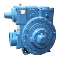
b. To remove the mechanical seal, use two screw
drivers against the backside of the seal jacket to
gently push the seal from the head (see Figure 5.
Use care when placing the screw drivers to prevent
damage to the seal faces. Remove and discard the
seal O-rings.
Figure 5 – Mechanical Seal Removal
10. Pull the rotor and shaft (13) from the cylinder. While one
hand is pulling the shaft, the other hand should be
cupped underneath the rotor to prevent the vanes (14)
and push rods (77) from falling out. Carefully set the rotor
and shaft aside for future vane replacement and
reassembly.
11. Remove the remaining components from the outboard
side of the pump, as instructed in steps 7 and 8 above.
PARTS REPLACEMENT
1. If any of the O-rings have been removed or disturbed
during disassembly, they be replaced with new O-rings.
NOTE: PTFE O-rings should be heated in hot water to
aid installation.
2. Excessive or continuous leakage from the tell-tale hole in
the bearing cover may be an indication of a damaged
mechanical seal. If a mechanical seal has been leaking, it
is recommended the entire seal be replaced. Refer to
"General Pump Troubleshooting" for possible causes of
seal leakage.