EN
20mm
16mm
10
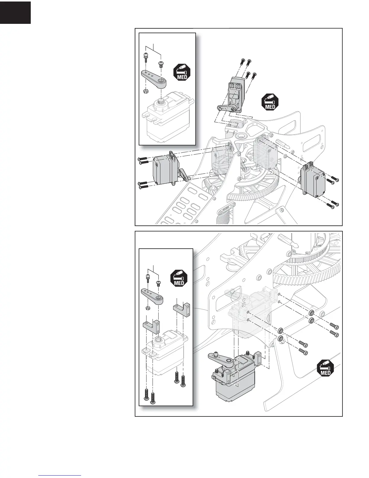
Prepare three cyclic servos as follows:
1. Center the servos using either your receiver or a
servo tester.
2. Attach the servo arm in the position shown,
perpendicular to the servo case, using the screw
provided with the servo and medium thread-locking
compound.
3. Attach the linkage ball to the outer servo arm
location using an M2 nut.
4. Attach the servos to the bearing blocks, in the
positions shown using 3x10mm button head screws
and medium thread-locking compound.
5. Press the bottom end of the servo linkages on the
servo arm linkage balls.
Prepare the tail servo as follows:
1. Center the servo using either your receiver or a
servo tester.
2. Attach the servo arm in the position shown,
perpendicular to the servo case, using the screw
provided with the servo and medium thread-locking
compound.
3. Attach the linkage ball to the middle servo arm
location, using an M2 nut.
4. Attach the tail servo mounts to the servo using
M3x8mm button head screws and thread-locking
compound. Do not fully tighten the servo mount
screws.
5. Attach the tail servo assembly to the inside of the
right frame side as shown, using four 3x10mm
screws, machined washers and medium thread-
locking compound.
6. Fully tighten the servo mount screws.
Rotor head removed for clarity
Step F8
Step F9
 Loading...