1-7D Operating Instructions
Maintenance
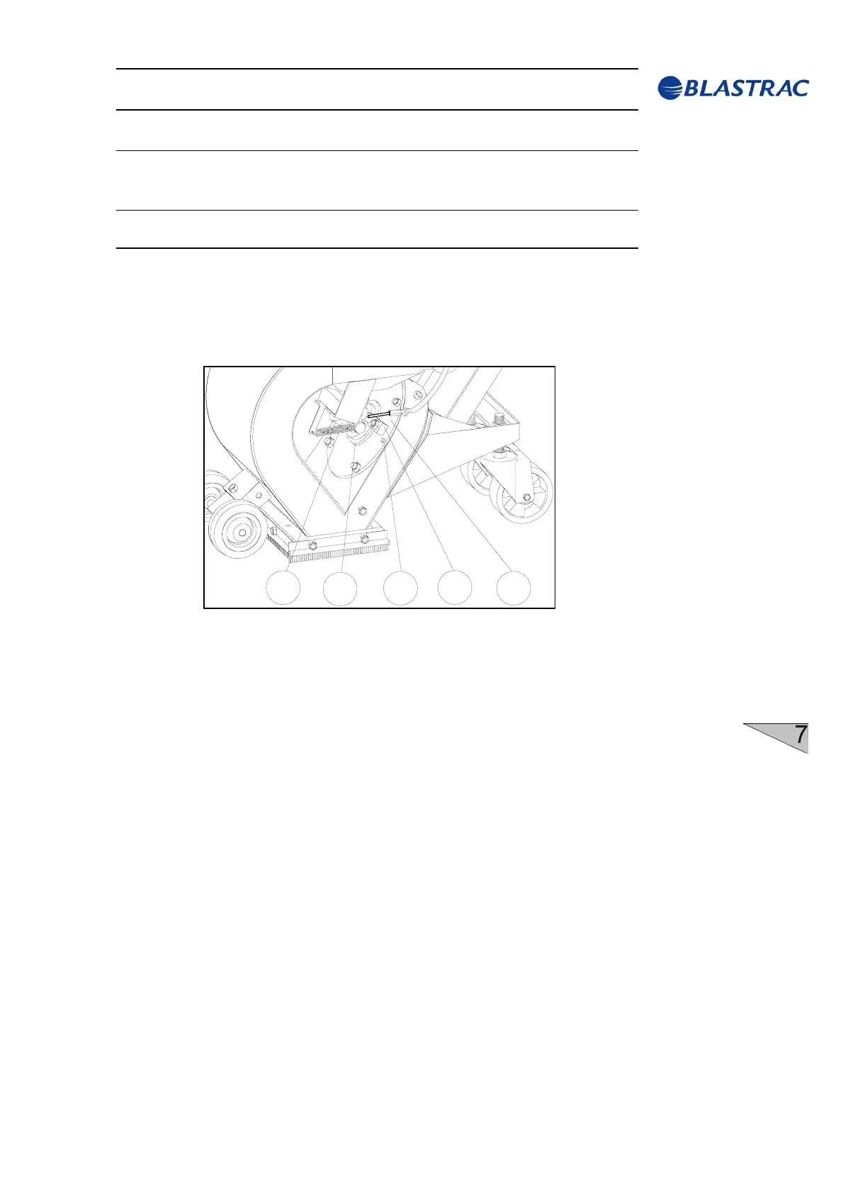
7.4 The blast pattern
Abrasive leaving the blast wheel blades is not thrown in all directions.
Scatter is restricted to an angle of about 50°. This is achieved through
the use of a control cage which surrounds the impeller. The position
of the window in the control cage determines the blast pattern.
5
2
3
4
1
Fig. 7.1
1 Feed spout
2 Control cage
3 Positioning pin
4 Cage clamp
5 Cage retaining plate with positioning hole
The position of the control cage has been set by ISPC Blastrac/EBE
and is fixed by pins and recesses.
Do not remove any fixings. Incorrect adjustment of the control cage
results in very high wear and premature blasting-through of the liners in
the blast wheel housing, as well as reduced blasting performance and a
possible loss of the rebounce energy of the abrasive.
Every time the control cage is replaced, the thread of the blast wheel
fastening nut should be checked. Make sure that this nut will be
tightened correctly. In addition, absolute care must be taken to clean
the thread from dust and abrasive.
5


 To Next Page