Do you have a question about the BMS HELI-CODER 4 and is the answer not in the manual?
Discusses RF hazards, non-ionizing radiation, and FCC exposure limits for operator safety.
Provides essential safety guidelines for operating the transmitter, including handling cables and equipment.
Details the technical specifications of the Heli-Coder 4 transmitter, including frequency, power, and modulation.
Lists the available part numbers, models, and profiles for the Heli-Coder 4 transmitter.
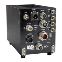
Details pinouts and descriptions for Power, Ethernet, COM, and GPS connectors.
Details pinouts for RF Output, Audio, Control, and ARINC connectors on the HC4.
Details pinouts for CVBS, ASI, HD/SDI video, and USB 2.0 connectors.
Covers component placement, fasteners, and transmitter mounting procedures, ensuring proper airflow.
Details power input and RF output connections, including cable recommendations and best practices.
Details video (SDI, CVBS), ASI, audio input, and GPS antenna connection interfaces.
Details data wayside, KLV, auxiliary data, Ethernet, USB, ARINC, and control interfaces.
Instructions for operating the HC4 transmitter using the DLC50 control panel, including power-on and basic controls.
Explains the menu structure and commands available on the DLC50 control panel for transmitter operation.
Describes the Geo-Point system for tracking aircraft range and direction using real-time video and GPS data.
Explains how to enable the Geo-Point function, detailing GPS sources and data requirements.
Provides step-by-step instructions for updating software on the DLC50 and HC4 via USB.
Details EU electromagnetic compliance and FCC authorization status for the HC4 transmitter.
Lists RTCA DO-160G sections the HC4 and DLC50 are designed to meet.
Provides a schedule and outlines specific procedures for recommended preventive maintenance tasks.
States that the HC4 has no user-replaceable parts and advises contacting BMS for service.
Provides contact information for BMS customer service for warranty repairs and inquiries.
| Brand | BMS |
|---|---|
| Model | HELI-CODER 4 |
| Category | Transmitter |
| Language | English |