Heli-Coder 4 Transmitter Operation Manual | Doc. No. 6051452100 Rev. C
Broadcast Microwave Services, Inc. 4
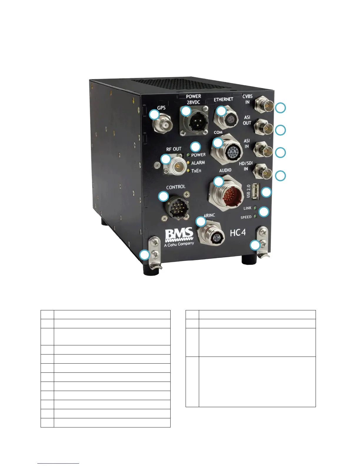
3 PRODUCT DEFINITION
Figure 1. Heli-Coder 4 Transmitter
Table 2. Product connector descriptions in Figure 1
Communications Port Connector – RS-232
Control cable Input (from DLC50 Control Panel)
ARINC Connector (Reserved for future use)
Analog Video Input (CVBS composite video)
ASI (Asynchronous Serial Interface) video out
ASI (Asynchronous Serial Interface) video in
HD/SDI (Digital –uncompressed) video in
Ethernet Status Indicators: Yellow SPEED LED:
ON=100BaseT, OFF=10BaseT Green LINK LED:
Flashing=Valid Ethernet Link, Off=NO Valid
Ethernet Link
Power LED: YELLOW when power cable
plugged in; GREEN when unit turned on via
DLC50 Control Panel
Alarm LED: YELLOW indicates a transmit
problem
TxEn LED (Transmit Enabled): YELLOW means
Standby mode; GREEN means transmitter active