Heli-Coder 4 Transmitter Operation Manual | Doc. No. 6051452100 Rev. C
Broadcast Microwave Services, Inc. 7
5 INSTALLATION
Installation should only be performed by an FAA Certified A/P or Avionics Technician.
The HC4 and associated equipment should be installed in compliance with FAA regulations and accepted industry
practices.
Other than allowing adequate air circulation above and below the transmitter, there are no set standards for
placement of the HC4 equipment. The information in Table 5 is a guide for choosing the best placement for each
component. Every aircraft installation is different, with unique interior space requirements to meet the needs of the
pilot, operator and passengers. It is left to the customer to review the size, space, cable and ergonomic needs to
best determine where the components should be installed.
The HC4 may be ordered with the HC4-CONN-KIT which contains all mating connectors except those
locally available (BNC, N, and USB). Alternatively BMS will supply a partially assembled wiring harness upon
order request.
Consult BMS regarding custom cable requirements
5.1 Locating the Components
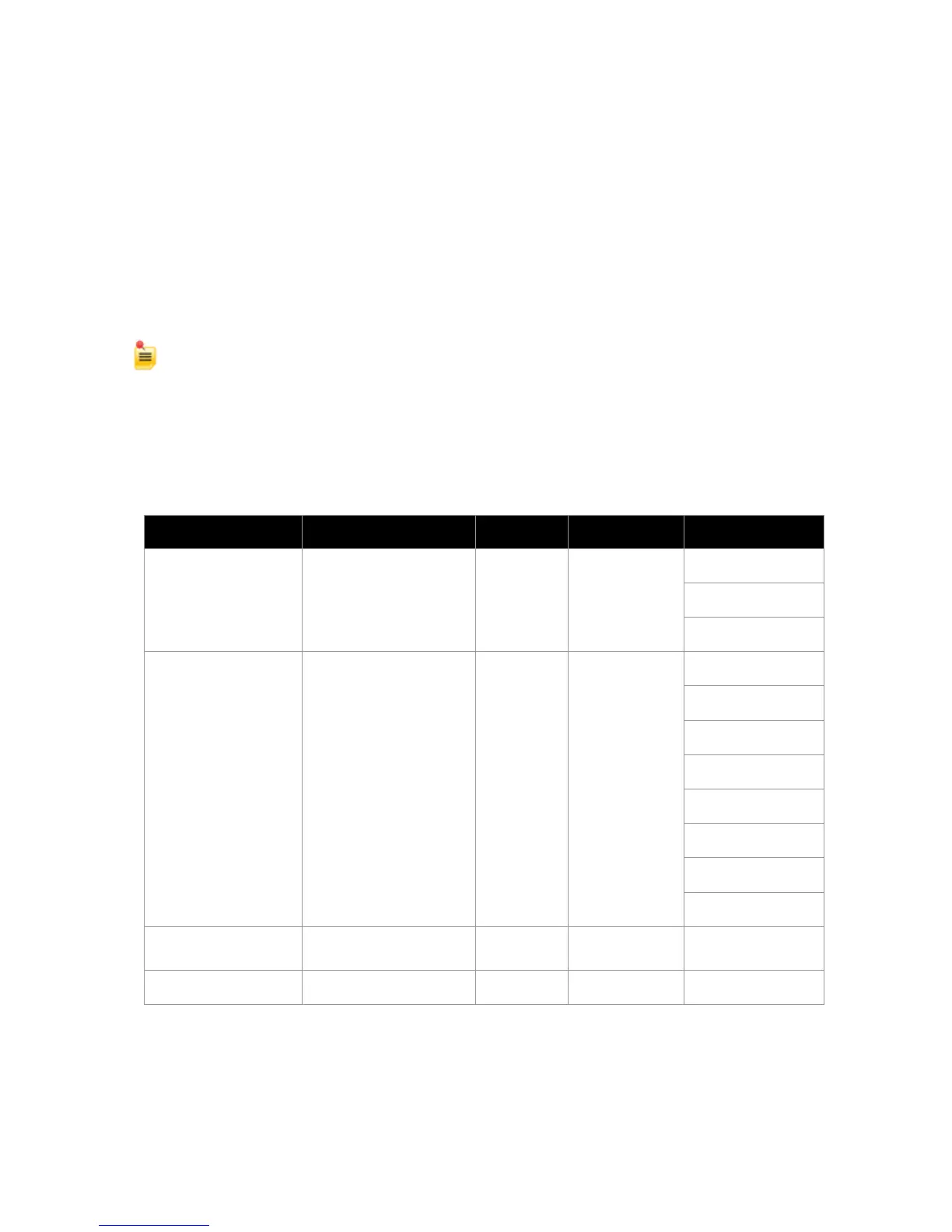
Table 5. HC4 Component Placement Planning
DLC50 Primary
Airborne Control
Panel
4.9 in. x 5.75 in. x 1.5 in.
12.4 cm x 14.6 cm x 3.8 cm
HC4 TRANSMITTER
(with CT-A-MP
mounting tray)
5“ W x 9“ D x 6“ H
(127 x 229 x 153 mm)
Usually baggage
compartment but
varies. Allow
ventilation space
above and below
transmitter
Unobstructed View
5 in. x 3 in. footprint
12.7 cm x 7. 6cm
Top Exterior
Tail (Varies)
Exterior Location
(Varies)