Broadcast Microwave Services, Inc. iv
List of Figures
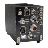
Figure 1. Heli-Coder 4 Transmitter ............................................................................................................................ 4
Figure 2 HC4 Front Panel Labels .............................................................................................................................. 3
Figure 3 Transmitter mounting bracket ..................................................................................................................... 8
Figure 4 HC4 positioned in aircraft mounting bracket ................................................................................................ 8
Figure 5 HC4 Outline Drawing ................................................................................................................................... 9
Figure 6 CT-A-MP HC4 Mounting Plate - Dimensioned Drawing ............................................................................ 10
Figure 7 DLC50-A AVIONICS CONTROL PANEL (FRONT) ................................................................................... 13
Figure 8 DLC50-A AVIONICS CONTROL PANEL (BACK)...................................................................................... 13
Figure 9 DLC50 Commands .................................................................................................................................... 14
Figure 10 DLC50 Outline ......................................................................................................................................... 15
Figure 11 Product Label........................................................................................................................................... 21
Figure 12 Typical airborne installation diagram (without TAA-101 Antenna Actuator) ............................................. 25
Figure 13 Wire Hook-Up Diagram for HC4 System (without TAA-101 Antenna Actuator) ....................................... 26
Figure 14 Typical airborne installation diagram (including TAA-101 Antenna Actuator) .......................................... 27
Figure 15 Wire Hook-Up Diagram for HC4 System (including TAA-101 Antenna Actuator) .................................... 28
List of Tables
Table 1 MPE per FCC OET65 (1.5 GHz to 100 GHz) ................................................................................................ 3
Table 2. Product connector descriptions in Figure 1 .................................................................................................. 4
Table 3. HC4 connectors ........................................................................................................................................... 3
Table 4. Connector pin outs ....................................................................................................................................... 4
Table 5. HC4 Component Placement Planning ......................................................................................................... 7