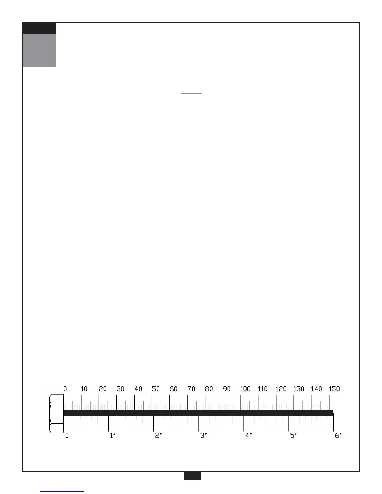
mm
Inch
2
Be careful to assemble all components
in the sequence they are presented.
12
STEP
A. Attach one End Cap (4) to the front of Top Frame (E).
Attach one End Cap (4) to the small horizontal arm sticking out of the Angled Vertical
Frame (D) as shown.
B. Attach Front Frame (F) to Main Base Frame (A) using:
One 62 (3/8”x 2 1/2” hex head bolt)*
Two 55 (3/8” washer)
One 51 (3/8” nylon lock nut)
Attach Flat End Cap (2) into the opening in the Front Frame (F).
*NOTE:
Only use one bolt (62) as shown. You will need the other hole open for step 3.
C. Insert two Thin Nylon Bushings (7) into Back Pad Adjuster (G).
Attach Back Pad Adjuster (G) to Angled Vertical Frame (D) using:
Two 40 (1/2” x 3” hex head bolt)
Two 54 (1/2” washer)
Two 50 (1/2” nylon lock nut)
NOTE:
Finger tighten all hardware in this step. Do Not
wrench tighten until end of step 4.