12
Be careful to assemble all components
in the sequence they are presented.
STEP
Note:
All Pulleys in this step are 4 1/4” diameter.
Leave all pulley bolts hand tight until step 13 is completed.
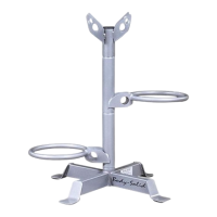
A. See Diagram 1. Route Cable (67) up
and through Double Pulley Holder (X). Route Cable (67)
around Pulley (B4) and install Pulley (B4) using:
One 44 (3/8” x 1 1/2” hex head bolt)
One 51 (3/8” nylon lock nut)
B. See Diagram 1. Route Cable (67) through Pulley Holder (Y). Route Cable (67) around Pulley (B5)
and install Pulley (B5) using:
One 44 (3/8” x 1 1/2” hex head bolt)
One 51 (3/8” nylon lock nut)
C. Insert Cable (67) through Angled Vertical Frame (D) and install Pulley (B6) under Cable (67) as
shown using:
One 43 (3/8” x 2 3/4” hex head bolt)
Two 15 (nylon bushing)
One 51 (3/8” nylon lock nut)
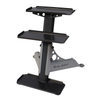
D. See Diagram 1A. Attach Short Cable (68) to Main Base Frame (A) using:
One 43 (3/8” x 2 3/4” hex head bolt)
One 55 (3/8” washer)
One 51 (3/8” nylon lock nut)
F. See Diagram 1A. Attach the other end of Cable (68) to the hook on the bottom of Pulley
Holder (Y).
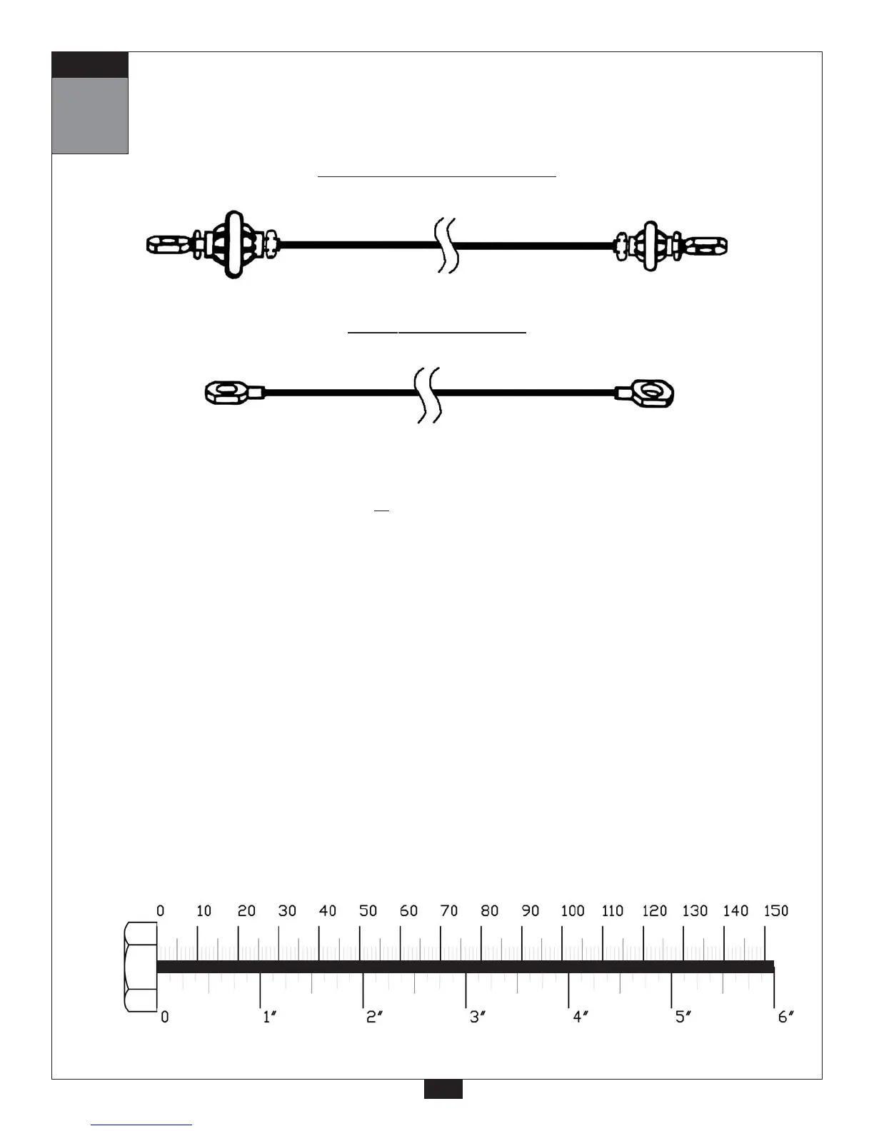
mm
Inch
32
Low Pulley Cable (67)
Ball Stop End
Threaded End
4030 mm
13’ 2.5”
Short Cable (68)
Stamped Eye End
Stamped Eye End
595 mm
1’ 11.5”