Ailerons:
Number
.......... . .......
...
.. ..
.......
..
.
.. ..
...
...........
...
.
....
.
....
..
..
..
..
...
..............
..
.... 2
Area
..........
...
...
..
....
..
......
.....
..
..
...
.
..
.
..
.
..
.
..
.....................
..
.
...
...
.....
..
.....
...
..
..
..
..
.
...
.
..
13.8
sq.
ft.
Stabilizer:
Area
......
..
....... .................
..
.
..
.
...
.........
..
: .
...
..
.......
....
..
.
..
.
..
...........
...
........
...
............ 20.9
sq.
ft.
Setting
..
..........
....
...
.....
....
..
....
..
.........
..
.
..
...
.
...
......
.
..
............
...
.........
..
..
..
...
.....
..
..
..
+2
°
to
---4°
Elevator:
Area
..
........... . . ...... .
..
...
..............................
..
.
...
.. ..
.
....
..
............... 13.4
sq.
ft.
Fin:
Area
.............. .
1.8
sq.
ft.
Rudder:
Area
....... ..............
..
........................................... .....................
..
..... .
8.2
sq.
ft.
Landing Gear:
Tread
.
..
..................................
..
..
..
...
....
.
...
..................
..
.....................
....
..
.....
..
.....
6 f t.-3 in.
Wheels
ahead
of
center
of
gravity
(normal).
...
..
..
....
....
...
.
...
.
..
..
......
.
...
..
...
.
18
.88 in.
SECTION
II
WINGS
Para
grap
h
Page
3.
Assembly
and
Alignment
.
..
..
.... .. .. ..
..
...
.
..
...
....
......................
..
....
..........
..
.......
..
............
..
6
4.
Disassembly.
..
....
..
.....
..
.
.. ..
....
.........
..
..........
..
.....
..
.....
..
....
...........
..
..
..
..
..
.......
..
..
..
........
.. ....
.... 8
5.
Maintenance
........ ..........
....
..
..
.
...
.......................................
...
......
....
.
..
.
...
..
...
........................ 8
3.
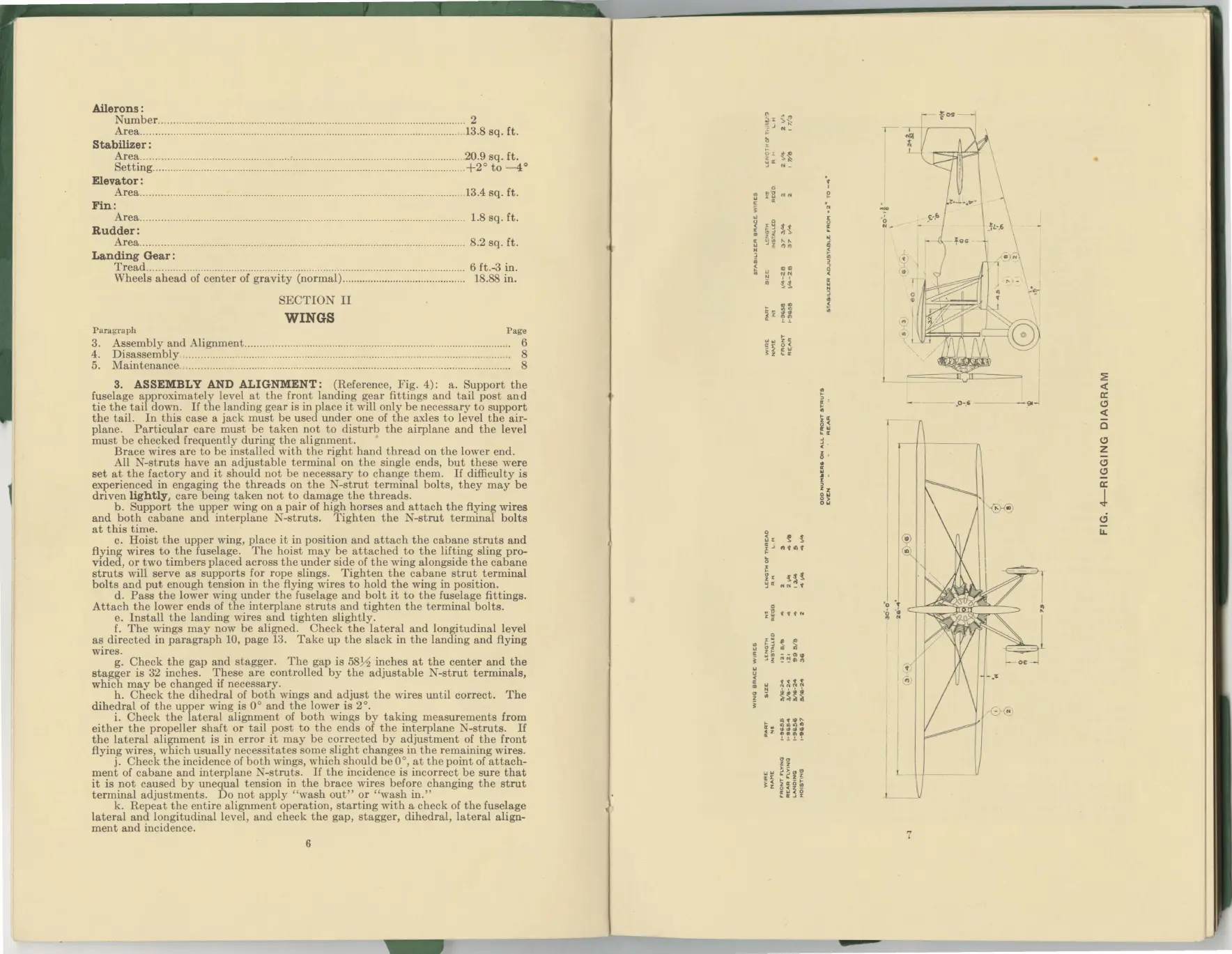
ASSEMBLY AND ALIGNMENT: (Reference,
Fig.
4):
a.
Support
the
fuselage
approximately
lev
el
at
the
front
landing
gear
fittings
and
tail
post
and
tie
the
tail
down. If
the
landing
gear
is
in
place
it
will
only
be
necessary
to
support
the
tail.
In
this
case
a
jack
must
be
used
under
one of
the
axles
to
level
the
air-
plane.
Particular
care
must
be
taken
not
to
disturb
the
airplane
and
the
level
must
be
checked
frequently
during
the
alignment.
Brace
wires
are
to
be
installed
with
the
right
hand
thread
on
the
lower
end.
All
-struts
have
an
adjustable
terminal
on
the
single ends,
but
these
were
set
at
the
factory
and
it
should
not
be
necessary
to
c
hange
them.
If
difficulty
is
experienced
in
engaging
the
threads
on
the
N-strut
terminal
bolts,
they
may
be
driven
lightly,
care
being
taken
not
to
damage
the
threads.
b.
Support
the
upper
w
ing
on
a
pair
of
high
horses
and
attach
the
flying
wires
and
both
cabane
and
interplane
N-struts.
Tighten
the
N-strut
terminal
bolts
at
this
time.
c.
Hoist
the
upper
wing,
place
it
in
position
and
attach
the
cabane
struts
and
flying
wires
to
the
fuselage.
The
hoist
may
be
attached
to
the
lifting
sling
pro-
vided,
or
two
timbers
placed
across
the
under
side
of
the
wing
alongside
the
cabane
struts
will
serve
as
supports
for
rope
slings.
Tighten
the
cabane
strut
terminal
bolts
and
put
enough
tension
in
the
flying
wires
to
hold
the
wing
in
position.
d.
Pass
the
lower
wing
under
the
fuselage
and
bolt
it
to
the
fuselage
fittings.
Attach
the
lower
ends
of
the
interplane
struts
and
tighten
the
terminal
bolts.
e.
Install
the
landing
wires
and
tighten
slightly.
f.
The
wings
may
now
be
aligned
.
Check
the
lateral
and
longitudinal
level
as
directed
in
paragraph
10,
page
13.
Take
up
the
slack
in
the
landing
and
flying
wires.
g.
Check
the
gap
and
stagger.
The
gap
is
58½
inches
at
the
center
and
the
stagger
is
32
inches.
These
are
controlled
by
the
adjustable
N-strut
terminals,
which
may
be
changed
if
necessary.
h.
Check
the
dihedral
of
both
wings
and
adjust
t
he
wires
un
t
il
correct.
The
dihedral
of
the
upper
wing
is
O
O
and
the
lower
is
2 °.
i.
Check
the
lateral
alignment
of
both
wings
by
taking
measurements
from
either
the
propeller
shaft
or
tail
post
to
the
ends
of
the
interplane
N-struts.
If
the
lateral
alignment
is
in
error
it
may
be
corre
c
ted
by
adjustment
of
the
front
flying
wires,
which
usuall
y
ne
c
essitates
some
slight
changes
in
the
remaining
wires.
j.
Check
the
in
c
id
e
nce
of
both
wings,
whi
ch
should
be 0
°,
at
the
point
of
attach-
ment
of
cabane
and
interplane
-struts.
If
the
inciden
ce is
incorrect
be
sure
that
it
is
not
caused
by
unequal
tension
in
the
brace
wires
before
changing
the
strut
terminal
adjustmen
ts.
Do
not
apply
"wash
out"
or
"
wa
sh in."
k.
Repeat
the
entire
alignment
operation,
starting
with
a
check
of
the
fuselage
lateral
and
longitudinal
level
,
and
check
the
gap,
stagger,
dihedral,
lateral
align-
ment
and
incidence.
6
z
..
~
It
L
-g
-*
l_
7
- .
o-
.6
--
-~-
~
<(
er:
c.,
<(
0
c.,
z
c.,
c.,
er:
J
d
LL.
 Loading...


