Orion ISS
www.bolid.com 66
CONNECTING ALARM LOOPS
In all S2000-2 operation modes except the Swing-beam Barrier (see above) LOOP1 and LOOP2 ter-
minals of the S2000-2 controller are used to connect intruder alarm loops (see Alarm Loops Section
of this Manual).
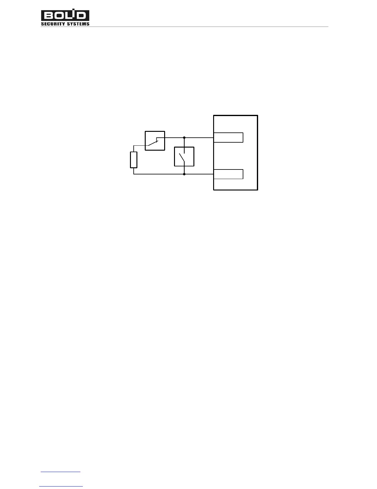
Figure 17 shows how to bring detectors with normally closed and normally open contacts into a
S2000-2 alarm loop.
8.2 kOhm
LOOP
S2000-2
LOOP+
Figure 17. NO and NC Intruder Detectors to the S2000-2 Connection Diagram
Resistance of the loop wires must not exceed 1 kOhm, excluding the terminating resistor.
Leakage resistance between the loop wires or between each wire and ground must not be less than
20 kOhm.
The S2000-2 controller provides arming a loop if the resistance of this loop including terminating re-
sistance 8.2 kOhm ranges from 5 kOhm ± 10% to 11 kOhm ± 10%.