6
Keyboard Diagrams
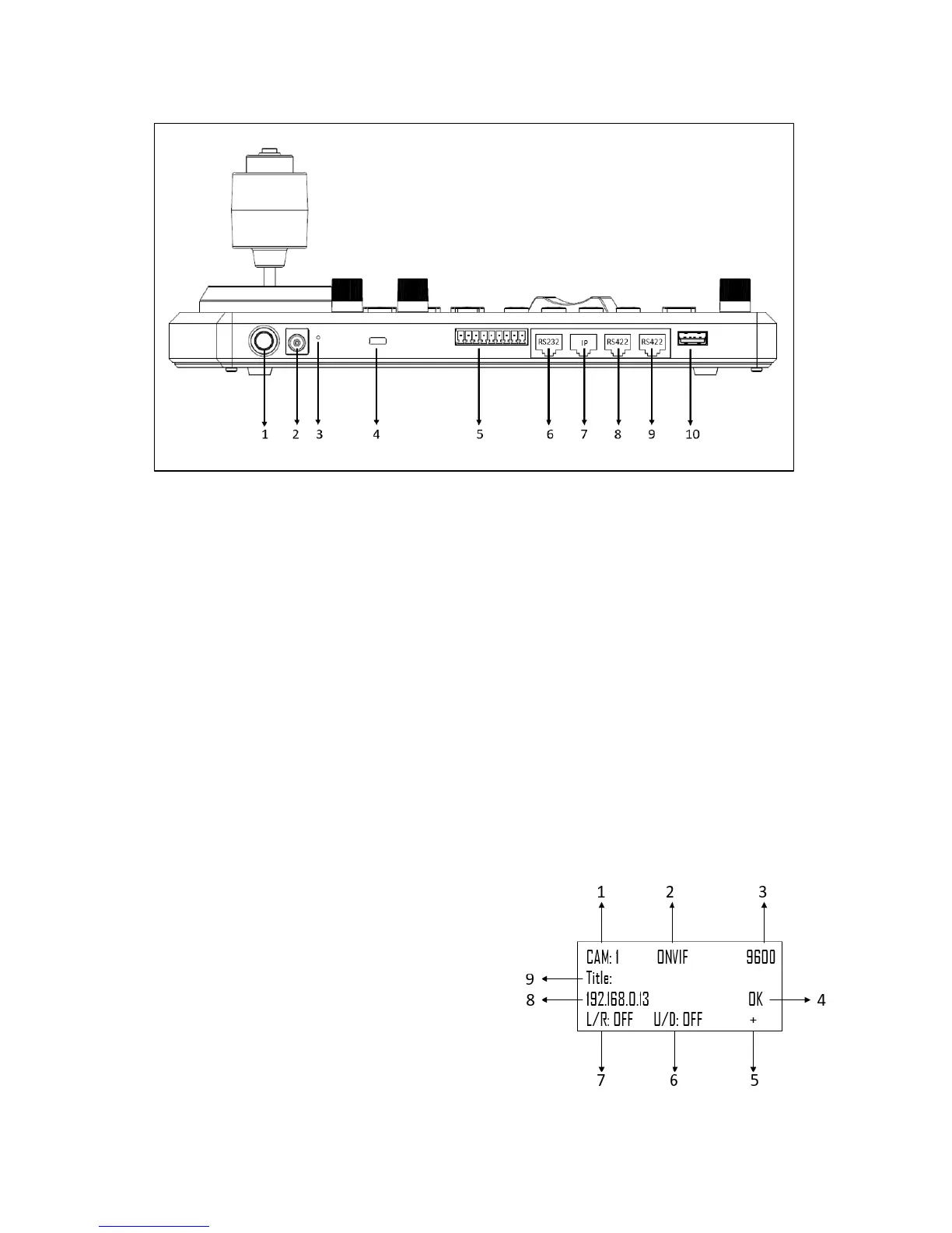
KBD-1010
1. Power Button
Power on / Power off the keyboard
2. 12V DC Power Port, wide range input tolerance from 5V-48VDC
Connect the supplied DC power adaptor and cord
3. Firmware Interface Button
Engages firmware update mode on the keyboard
4. Kensington Security slot
Use a lock to physically secure the keyboard in place
5. Tally / Contact (GPI I/O connector)
Tally control interface
6. RS232 interface / RJ-45 port
Connect RS232 adapter
7. IP Interface / RJ-45 port
Connect the keyboard to a network
8. RS422 (B) interface, use for RS485 as well / RJ-45 port
Connect an RS422 adapter to control up to 7 daisy-chained RS422 cameras (Group A)
9. RS422(A) interface, use for RS485 as well / RJ-45 port
Connect an RS422 adapter to control up to 7 daisy-chained RS422 cameras (Group B)
10. Firmware Upgrade USB port
Home Screen
1. Camera Identifier – Identifies which camera is being
controlled, and the protocol being used
2. Protocol
3. Baud Rate
4. Communication indicator for current device
5. Network Connectivity indicator
a. If the “+” appears, this means that the network
is successfully connected
b. If the “+” does not appear, this means that the
network is not connected
6. Tilt Reversal Indicator
7. Pan Reversal Indicator
8. IP Address
9. Camera Title