Modbus Instruction manual 3305/08
05/08
Modbus Instruction manual 33
6.7.2 ASCII Transmission
When devices are setup to communicate on a MODBUS serial line using 7-bit ASCII
(American Standard Code for Information Interchange) mode, each 8 bit character in
a message is sent as two ASCII characters. This mode is used when the physical
communication link or the capabilities of the device does not allow the conformance
with RTU mode requirements regarding timers management.
Remark: this mode is less efficient than RTU since each byte needs two characters.
Example: The byte 0x5B is encoded as two characters: 0x35 and 0x42 ( 0x35 ="5",
and 0x42 ="B" in ASCII ).
6.7.2.1 Character Format
One character consists of 10 bits:
− 1 start bit
− 7 data bits, least significant bit sent first (value = 0x00 .. 0x7F)
− 1 parity bit
− 1 stop bit
Note If no parity is used then an extra stop bit is added.
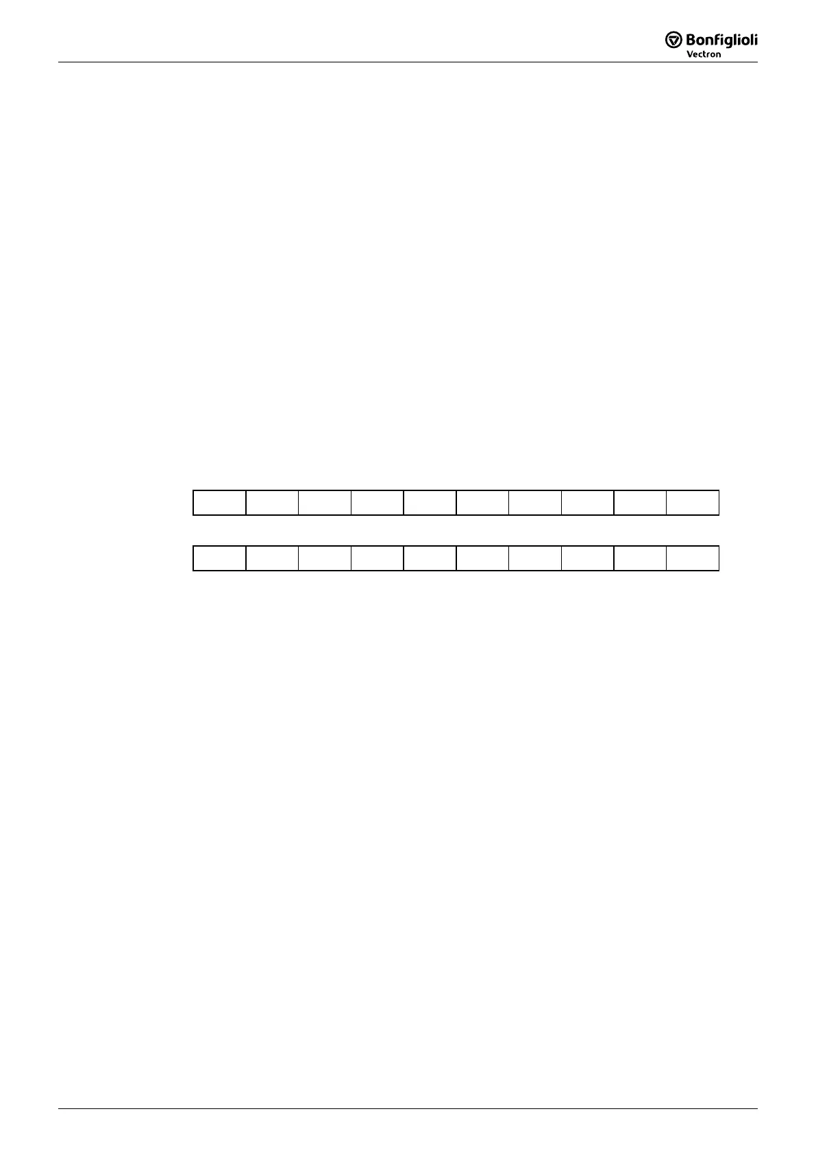
Character format with parity checking:
Start B1 B2 B3 B4 B5 B6 B7 Parity Stop
Character format without parity checking:
Start B1 B2 B3 B4 B5 B6 B7 Stop Stop
6.7.2.2 Modbus Message ASCII Framing
A MODBUS message is placed by the transmitting device into a frame that has a
known beginning and ending point. This allows devices that receive a new frame to
begin at the start of the message, and to know when the message is completed.
Partial messages must be detected and errors must be set as a result.
The address field of a message frame contains two characters.
In ASCII mode, a message is delimited by specific characters as Start-of-Frame and
End-of-Frame. A message must start with a trigger “colon”- character (“:” = ASCII
0x3A) and ends with a “carriage return/line feed” pair (ASCII 0x0D and 0x0A).
The allowable characters transmitted for all other fields are hexadecimal 0–9, A–F
(ASCII coded). The devices monitor the bus continuously for the colon character.
When this character is received, each device decodes the next character until it de-
tects the End-of-Frame (EoF)-character.



 To Next Page