Modbus Instruction manual 7105/08
05/08
Modbus Instruction manual 71
10.2 Control via state machine
In the operation mode “control via state machine” (parameter Local/Remote 412 = 1)
the frequency inverter is controlled via
controlword
.
State transition 4 to state “Operation enabled” is only possible when:
Motion control configuration (
Configuration 30 = x40):
Î controller release at STOA and STOB is set.
In other configurations (non motion control,
Configuration 30 ≠ x40):
Î controller release at STOA and STOB is set AND (S2IND OR S3IND)
(S2IND = start clockwise/S3IND = start anticlockwise)
The behavior of transition 5 can be set via the parameter State transition 5 392.
Here, free stopping, shutdown via ramp (reversible) or DC braking (see Chapter
"Behavior in transition 5") can be used.
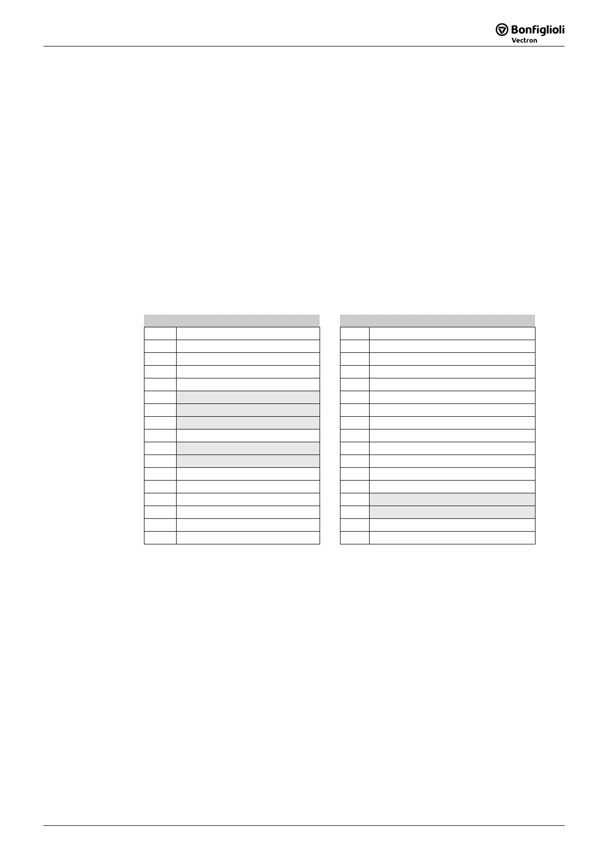
Control word 410 Status word 411
Bit Meaning Bit Meaning
0 Switch on 0 Ready to switch on
1 Enable voltage 1 Switched on
2 Quick stop 2 Operation enabled
3 Enable operation 3 Fault
4
Operation mode specific
4 Voltage enabled
5
Operation mode specific
5 Quick stop
6
Operation mode specific
6 Switch on disabled
7 Fault reset 7 Warning
8
Halt
8 Manufacturer specific
9
Operation mode specific
9 Remote
10
Reserved
10 Target reached
11
Manufacturer specific
11 Internal limit active
12
Manufacturer specific
12
Operation mode specific
13
Manufacturer specific
13
Operation mode specific
14
Manufacturer specific
14
Manufacturer specific
15
Manufacturer specific
15
Manufacturer specific
Warning2
Bits 9 … 15 unused Bit 14 unused
Controlword
bits 4, 5, 6
operation mode specific
and bit 8
halt
are used in motion
control configurations (
Configuration 30 = x40) only.
Statusword
bits 12 + 13
operation mode specific
are used in motion control configura-
tions (
Configuration 30 = x40) only.
Note: ACTIVE CUBE inverters support an external 24V supply for control logic. Even
if the mains are not switched on the communication between PLC and inverter
can be established.
The bit 4 “Voltage enabled” of the
statusword
displays the current state of
the mains power supply.
Bit 4 “Voltage enabled” = 0 signals “no mains voltage” and the state tran-
sision “Ready to switch on” Î “Switched on” is not possible.
Bit 4 “Voltage enabled” = 1” signals “mains voltage switched on” and the
state transition “Ready to switch on” Î “Switched on” is possible.
 Loading...