Modbus Instruction manual 05/0872
72
Modbus Instruction manual 05/08
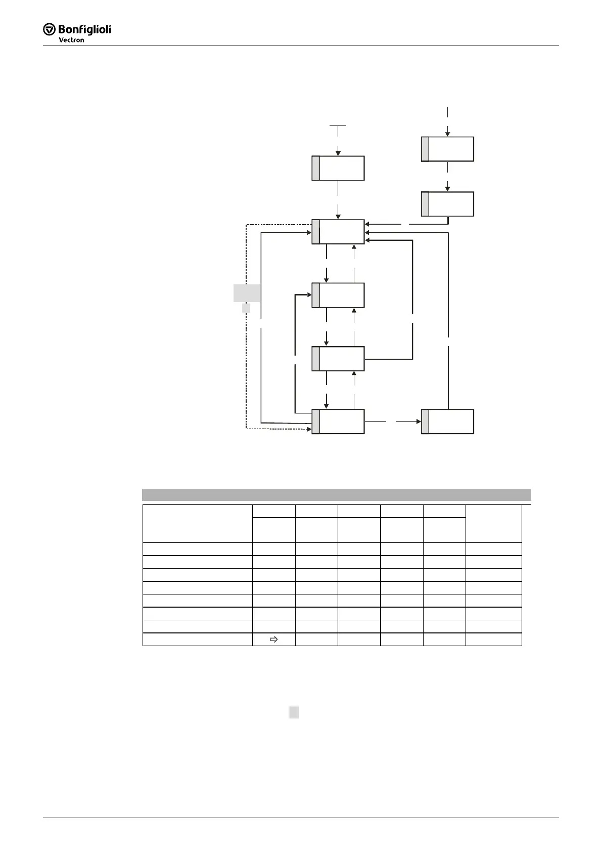
State machine:
4
Switched on
5
Operation
enabled
1
Not ready to
switch on
6
Quick stop
active
2
Switch on
disabled
3
Ready to
switch on
8
Fault
7
Fault reaction
active
1
2 7
3
6
14
13
0
Entry in state machine
from all state
s
15
12
10
4
5
11
8
9
Enable
operation
Disable
operation
Fault reset
Quick stop
Switch on
Shutdown
Shutdown
Shutdown
Disable
voltage
Disable v oltage
or Quick stop
Disable v oltage
or Quick stop
4’
Enable
operation
The device control commands are triggered by the following bit pattern in the
control-
word
:
Controlword
Bit 7 Bit 3 Bit 2 Bit 1 Bit 0
Command
Fault
reset
Enable
operation
Quick
stop
Enable
voltage
Switch on
Transitions
Shutdown X X 1 1 0 2, 6, 8
Switch-on X 0 1 1 1 3
Switch on X 1 1 1 1 3
Disable voltage X X X 0 X 7, 9, 10, 12
Quick stop X X 0 1 X 7, 10, 11
Disable operation X 0 1 1 1 5
Enable operation X 1 1 1 1 4
Fault reset 0 Ö 1 x x x x 15
Bits marked X are irrelevant
Note: The state transition 3 (command “Switch on”) is processed only if bit no. 4
“Voltage enabled” of the
statusword
is set.
The state transition 4’ is only available for non motion control configura-
tions (
Configuration 30 ≠ x40) and is processed only if bit no. 4 “Voltage
enabled” of the
statusword
is set. This function is for downward compati-
bility to older software versions.