Modbus Instruction manual 05/0880
80
Modbus Instruction manual 05/08
12 Annex
12.1 Warning Messages
The various control methods and the hardware of the frequency inverter include func-
tions which continuously monitor the application. In addition to the messages docu-
mented in the frequency inverter operating instructions, further warnin
g messages are
activated by the RS232/RS485 communication modules CM-232/CM-485.
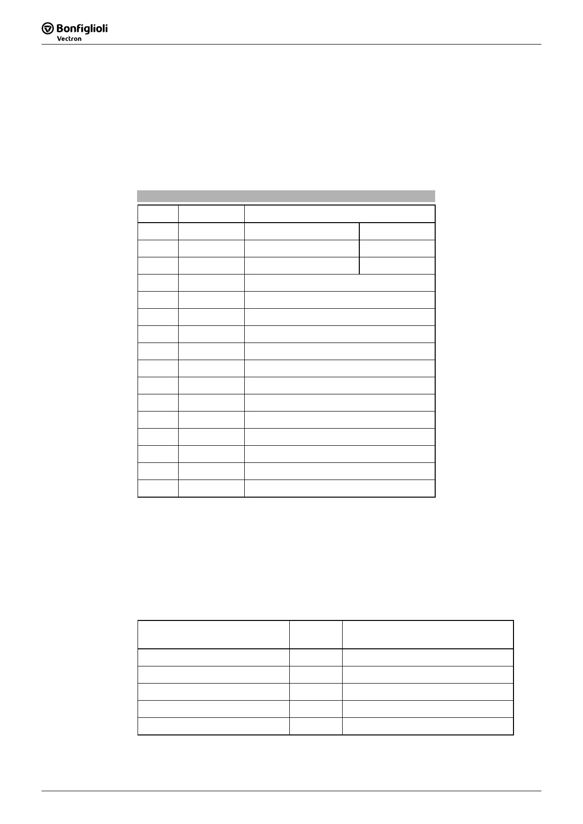
The bit-coded warning reports are issued via parameter
Warnings 270 according to
the following pattern:
Warning Messages
Bit no. Warning code Description
0
0x0001 Warning Ixt
1) 2)
1 0x0002
Warning Short-Term Ixt
1)
2 0x0004
Warning Long-Term Ixt
2)
3 0x0008
Warning Heat Sink Temperature Tk
4
0x0010 Warning Inside Temperature Ti
5 0x0020
Warning I-limit
6 0x0040
Warning Init
7 0x0080
Warning Motor Temperature
8 0x0100
Warning Phase Failure
9 0x0200
Warning Motor Protection Switch
10 0x0400
Warning Fmax
11 0x0800
Warning Analog Input MFI1A
12 0x1000
Warning Analog Input A2 (EM-S1INA)
13 0x2000
Warning System Bus Slave Failure
14 0x4000
Warning Udc
15 0x8000
Warning V-belt
1) 2)
Bit 0 "Warning Ixt" is always set
− if bit 1 "Warning Short-Term Ixt“ or
− if bit 2 "Warning Long-Term Ixt" is set.
Note: The individual warnings are described in detail in the frequency inverter
operating instructions.
Note: In parameter
Warnings 270 several warnings can be displayed at the
same time.
Example:
Message Warning
code
Remarks
Warning Ixt
0x0001
Is set in Short-Term Ixt or Long-Term Ixt
Short-Term Ixt
0x0002
Warning Limit Heat Sink Temperature
0x0008
Warning Motor Temperature
0x0080
Total
0x008B


 To Next Page