Modbus Instruction manual 05/0870
70
Modbus Instruction manual 05/08
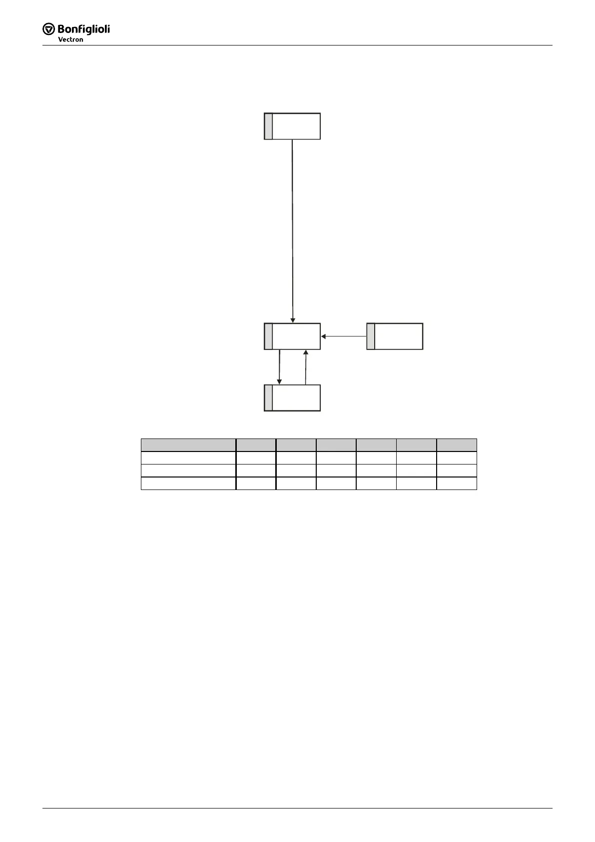
State machine:
4
switched on
5
operatio n
enabled
1
not ready to
switch on
8
fault
quitt fault
start drive
stop drive
Stateword Bit 5 Bit 4 Bit 3 Bit 2 Bit 1 Bit 0
Switched on 1 0 0 0 1 1
Operation enabled 1 1 0 1 1 1
Fault x x 1 x x x
Note: Bits marked “x” are don’t care.
The Warning bit "Bit No. 7" can signal an internal warning and results in the fre-
quency inverter being switched off, depending on the cause.
The evaluation of the warning is done by reading out the warning status via parame-
ter
Warnings 270.
The bit Target reached "Bit No. 10" is set when the reference value specified has
been reached. In the special case of power failure regulation, the bit is also set if the
power failure regulation has reached the frequency 0 Hz (see operating instructions).
For "Reference value reached“ there is a hysteresis (tolerance range), which can be
set via the parameter
max. Control deviation 549 (see operating instructions).
The bit Internal limit active "Bit No. 11" displays that an internal limit is active.
This can, for example, be the present current limit, the torque limit or the over-
voltage limit. All the functions lead to the reference value being quit or not reached.
The bit Warning 2 "Bit No. 15" reports a warning which leads to a fault switch-off
of the frequency inverter within a short time. This bit is set if there is a warning for
motor temperature, heat sink/inside temperature, Ixt monitoring or mains phase fail-
ure.
 Loading...