10
A
D
5
S3IND
4
S2IND
2
S1IND
7
S5IND
3
1
1
S6IND
GND 20 V
2
4
MFO1
S1OUT
3
CPU
+
-
L2 L3L1
X1
V
W
U
Rb1
X2
+
-
Rb2
I
U, I
A
B
C
D
E
F
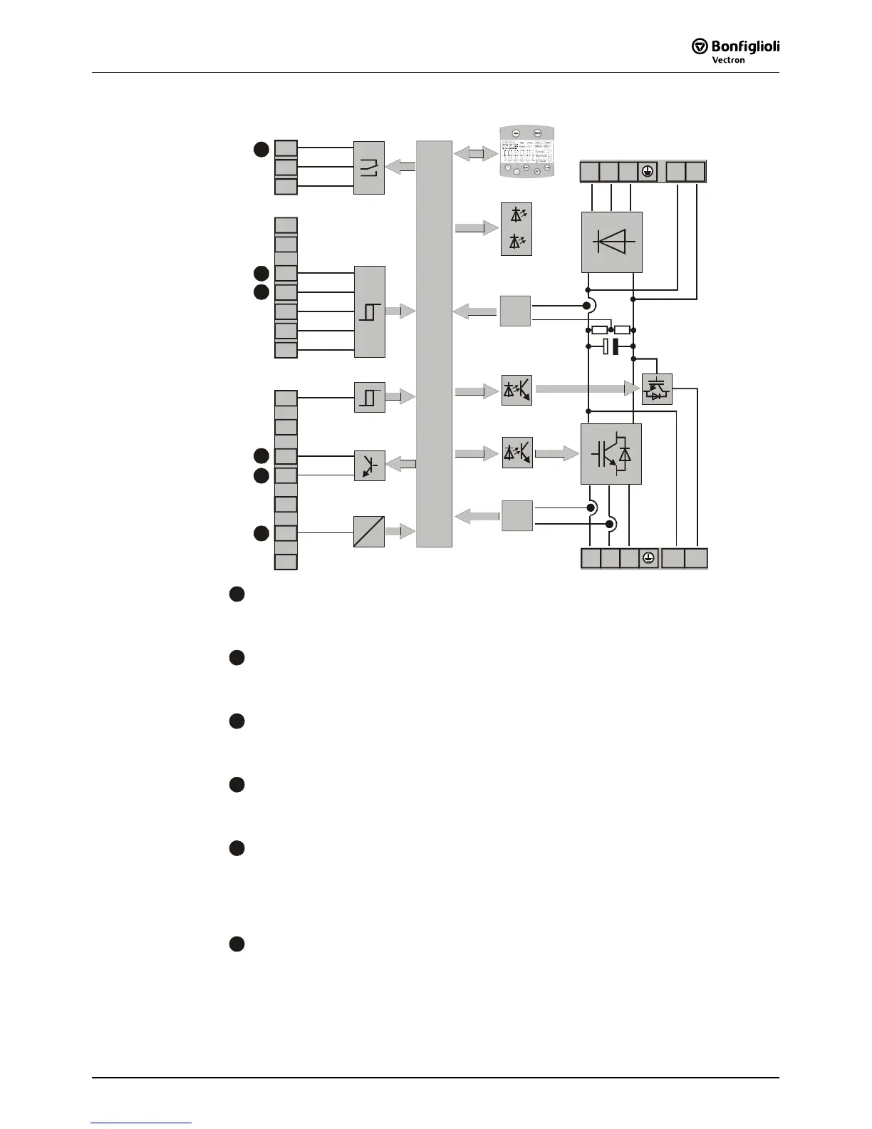
A
Relay connection S3OUT
Change-over contact, response time approx. 40 ms, 240 V AC / 5 A, 24 V DC / 5 A
(ohmic)
B
Digital input S1IND
Digital signal, controller enable signal, response time approx. 16 ms (on), 10 µs (off),
U
max
= 30 V, 10 mA at 24 V, PLC compatible
C
Digital input S2IND ... S6IND
Digital signal: response time approx. 16 ms, U
max
= 30 V, 10 mA at 24 V, PLC com-
patible, frequency signal: 0...30 V, 10 mA at 24 V, f
max
= 150 kHz
D
Digital output S1OUT
Digital signal, 24 V, I
max
= 40 mA,
PLC compatible, overload and short-circuit proof
E
Multi-function output MFO1
Analog signal: 24 V, I
max
= 40 mA, pulse-width modulated, f
PWM
= 116 Hz
Digital signal: 24 V, I
max
= 40 mA,
frequency signal: 0...24 V, I
max
= 40 mA, f
max
= 150 kHz,
PLC compatible, overload and short-circuit proof
F
Multi-function input MFI1
Analog signal: resolution 12 Bit, 0...10 V (Ri = 70 kΩ), 0...20 mA (Ri = 500 Ω),
digital signal: response time approx. 16 ms, U
max
= 30 V, 4 mA at 24 V,
PLC compatible

 Loading...


