7.2.7 Application data
With the frequency inverter, a great variety of different drive applications can be
realized. The parameter settings required for this often require the verification of
other parameters. The parameters polled during the guided commissioning procedure
were selected from standard applications.
After completion of commissioning, further parameters can be set in the PARA menu
branch.
7.2.7.1 Acceleration and deceleration
The settings define how fast the output frequency changes after a reference value
change or a start, stop or brake command.
Parameter Settings
No. Description Min. Max. Fact. sett.
420 Acceleration (Clockwise) 0.00 Hz/s 999.99 Hz/s 5.00 Hz/s
421 Deceleration (Clockwise) 0.00 Hz/s 999.99 Hz/s 5.00 Hz/s
Attention! The deceleration of the drive is monitored in the default parameter
setting
Operation Mode 670 for the Voltage Controller. The
deceleration ramp can be extended in the case of an increase in the DC
link voltage during regenerative operation and/or during the braking
process.
7.2.7.2 Set points at multi-functional input
The multi-functional input MFI1 can be parameterized for a reference value signal in
Operation Mode 452. Operation mode 3 should only be selected by expert users for
drive control via
Fixed Frequency 1 480 and Fixed Frequency 2 481.
Operation mode Function
1 - Voltage Input Voltage signal (MFI1A), 0V ... 10V
2 - Current Input Current signal (MFI1A), 0mA ... 20mA
3 - Digital Input Digital signal (MFI1D), 0V ...24V
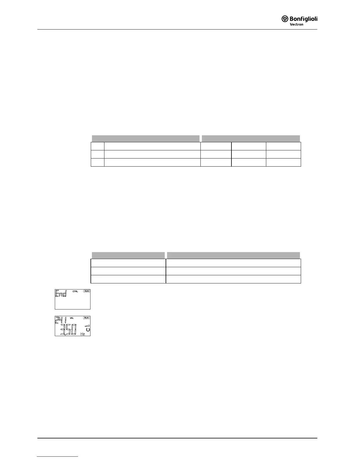
Confirm the "End" display by pressing the ENT key.
The guided commissioning of the frequency inverter is terminated via a reset and the
initialization of the frequency inverter. The relay output X10 signals a fault.
After successful initialization of the frequency inverter, the factory-set parameter
Actual Frequency 241 is displayed. If a signal is present at digital inputs S1IND
(controller release) and S2IND (start clockwise operation) or at digital inputs S1IND
(controller release) and S3IND (start of anti-clockwise operation), the drive is
accelerated to the adjusted
Minimum Frequency 418 (default value 3.50 Hz).

 Loading...


