Control terminal X210A
Ter. Description
1 Voltage output 20 V, I
max
=180 mA
1)
2 Ground / GND 20 V
3 Digital input S1IND, U
max
=30 V, 10 mA at 24 V, PLC compatible,
response time approx. 16ms (on), 10 µs (off)
4 Digital input EM-S2IND, U
max
=30 V, 10 mA at 24 V, PLC compatible,
response time approx. 16 ms
5 Digital input EM-S3IND, U
max
=30 V, 10 mA at 24 V, PLC compatible,
response time approx. 16 ms
6 Digital input S4IND, U
max
= 30 V, 10 mA at 24 V, PLC compatible,
frequency signal: 0...30 V, 10 mA at 24 V, f
max
= 150 kHz
7 Digital input S5IND, U
max
= 30 V, 10 mA at 24 V, PLC compatible,
frequency signal: 0...30 V, 10 mA at 24 V, f
max
= 150 kHz
Control terminal X210B
Ter. Description
1 Digital input S6IND, U
max
=30 V, 10 mA at 24 V, PLC compatible,
response time approx. 16 ms
2 Ground / GND 20 V
3 Digital output S1OUT, U=24 V, I
max
=40 mA, overload and short-circuit proof
4 Multi-function output MFO1,
analog signal: U=24 V, I
max
=40 mA, pulse-width modulated, f
PWM
=116 Hz
digital signal: U=24 V, I
max
=40 mA, overload and short-circuit proof,
frequency signal: 0...24 V, I
max
=40 mA, f
max
=150 kHz
5 Reference output 10 V, I
max
=4 mA
6 Multi-function input MFI1,
analog signal: resolution 12 Bit, 0...+10 V (Ri = 70 kΩ), 0...20 mA (Ri = 500 Ω),
digital signal: response time approx. 16 ms, U
max
= 30 V, 4 mA at 24 V,
PLC compatible
7 Ground / GND 10 V
1)
The power supply at terminal X210A.1 may be loaded with a maximum current
of I
max
= 180 mA. The maximum current available is reduced by the digital
output S1OUT and multifunctional output MFO1.
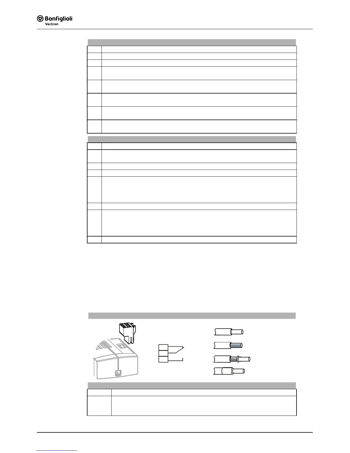
5.6.1 Relay Output
By default, the freely programmable relay output is linked to the monitoring function
(factory setting). The logic link to various functions can be freely configured via the
software parameters. Connection of the relay output is not absolutely necessary for
the function of the frequency inverter.
Relay Output
1
2
3
0.2 … 1.5 mm
AWG 24 … 16
2
Phoenix ZEC 1,5/3ST5,0
0.2 … 1.5 mm
AWG 24 … 16
2
0.25 … 1.5 mm
AWG 22 … 16
2
0.25 … 1.5 mm

 Loading...


