When an operation mode with motor chopper is selected, set the Trigger Threshold
507 < (Reference DC-Link Limitation 680 - 10 V). See chapter 18.7.1 “Motor Chop-
per”.
For synchronous motors (Configuration 30 = 5xx), the motor chopper function is de-
activated to prevent damages to the motor. The other functions of the voltage control-
ler are not affect
ed by this.
For asynchronous motors in V/f control (
Configuration 30
= 1xx), the motor chopper
function is not operative. The other functions of the voltage controller are not affected
by this.
The brake chopper is active dependent of the setting of Reference DC-Link Limitation
680
. See chapter 18.4 “Brake Chopper and Brake Resistance
” for parameterizing the
switching threshold.
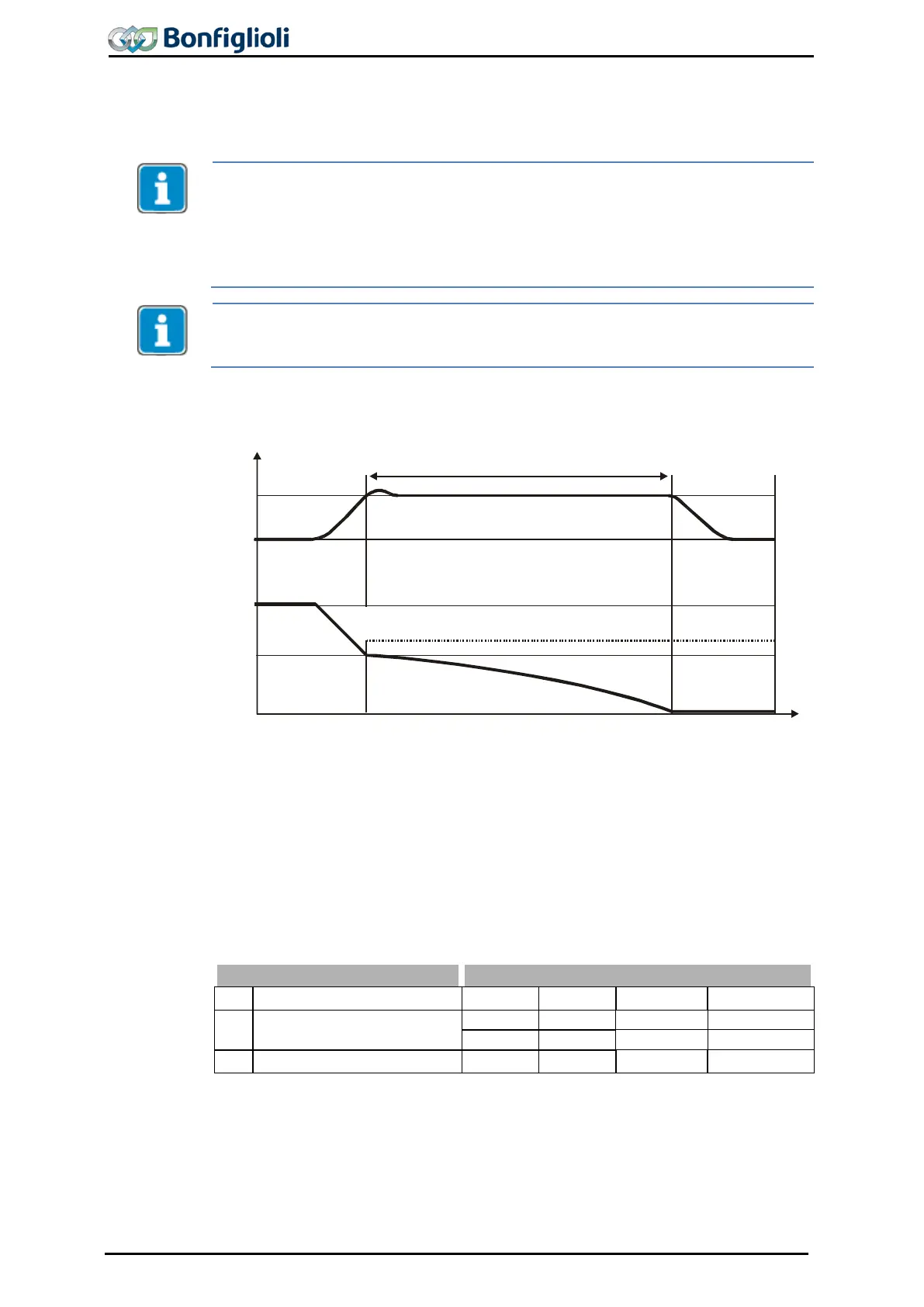
Operation mode Overvoltage control,
Voltage controller: Parameter Operation mode 670 = 1
Ud
Ud, f
681
f
t
421 or 423
680
Overvoltage controller active
The overvoltage controller prevents a switch-off of the frequency inverter in genera-
tor operation. The reduction of the drive speed by a ramp gradient selected via the
parameter Deceleration Clockwise 421 or Deceleration Anticlockwise 423
to an overvoltage in the DC link. If the voltage exceeds the figure set by the parame-
ter
Reference DC link limitation 680
, the deceleration is reduced in such a way that
the DC link voltage is regulated to the set value. If the DC link voltage cannot be
regulated to the set reference value by the reduction of the deceleration, the decel-
eration is stopped and the output frequency raised. The output frequency is calculat-
ed by addition of the parameter value
Max. Frequency Rise 681 to the frequency a
t
the operating point of the controller intervention.
680 Reference DC link limitation
681 Max. Frequency Rise 201/401 0.00 Hz 999.99 Hz 10.00 Hz
When an operation mode with motor chopper is selected, set the Trigger Threshold
507 < (Reference DC-Link Limitation 680 - 10 V). See chapter 18.7.1 “Motor Chop-
per”.
212 Operating Instructions ACU 06/13
 Loading...
