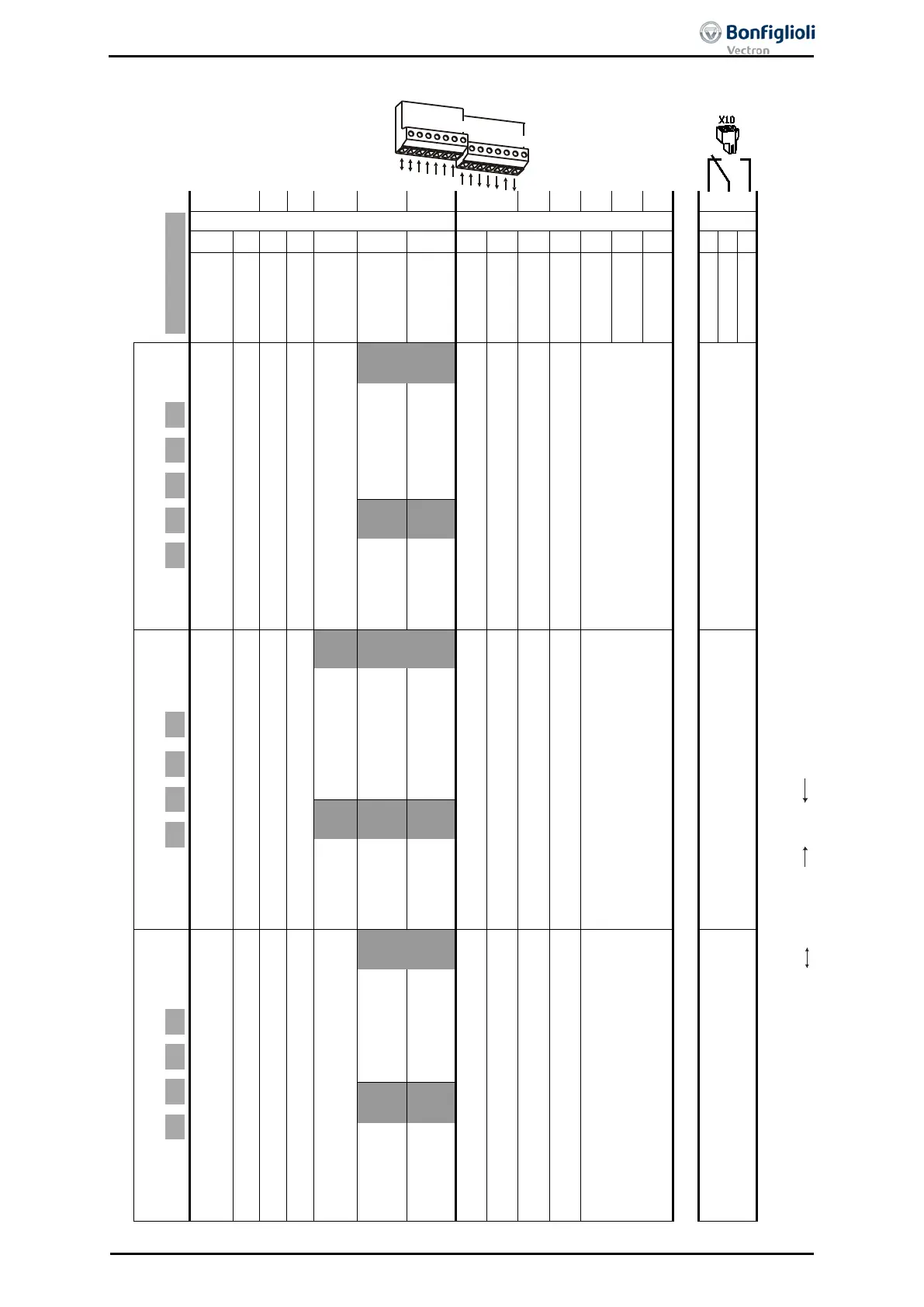
Functions of the control terminals (table)
Configuration 30
Bidirect. in in in in in in in out out out in out
1
2
3
4
5
6
7
1
2
3
4
5
6
7
DC 20 V out./
DC 24 V in
GND
S1IND
S2IND
S3IND
S4IND
S5IND
S6IND
S7IND
S1OUT
MFO1
DC 10 V out
MFI1
GND
S1IND … S7IND: Digital inputs, S1OUT: Digital outputs, MFO1: Multi-function output (factory setting as analog output), MFI1: Multi-function input (factory setting as ana-
log voltage input), S3OUT: Relay output, bidirectional, input, output, n.c.c: normally closed contact, n.o.c: normally open contact,
1)
Error acknowledgement via STOA or STOB,
2)
Linked to Timer 1 (
70 = “158 – Timer 1“,
83 = “73 – S4IND”, factory setting
791 = 0.00 s/m/h)
Functions of the control terminals in the standard configurations
Speed controlled
110 210 410 510 610
STOA/Error acknowledgement
1)
Start Clockwise operation
Start Anticlockwise operation
110
410
510
610
Motor thermal contact
STOB/Error acknowledgement
1)
Run signal
Actual frequency
Reference speed
Error signal, inverted
-
2)
-
210
210
Technology controller
111 211 411 611
STOA/Error acknowledgement
1)
Fixed percentage value change-over 1
111
111
411
611
Motor thermal contact
STOB/Error acknowledgement
1)
Run signal
Actual frequency
Actual percentage value
Error signal, inverted
Fixed percentage
value change-over 2
Data set change-
over 1
2)
Data set change-
over 2
411
211
211
Speed/Torque control change-over
230 430 530 630
STOA/Error acknowledgement
1)
Start Clockwise operation
Speed/Torque control change-over
430
530
630
Motor thermal contact
STOB/Error acknowledgement
1)
Run signal
Actual frequency
Reference speed or
Reference percentage value (torque)
Error signal, inverted
-
2)
-
230
230
06/13 Operating Instructions ACU 289
 Loading...
