11
11
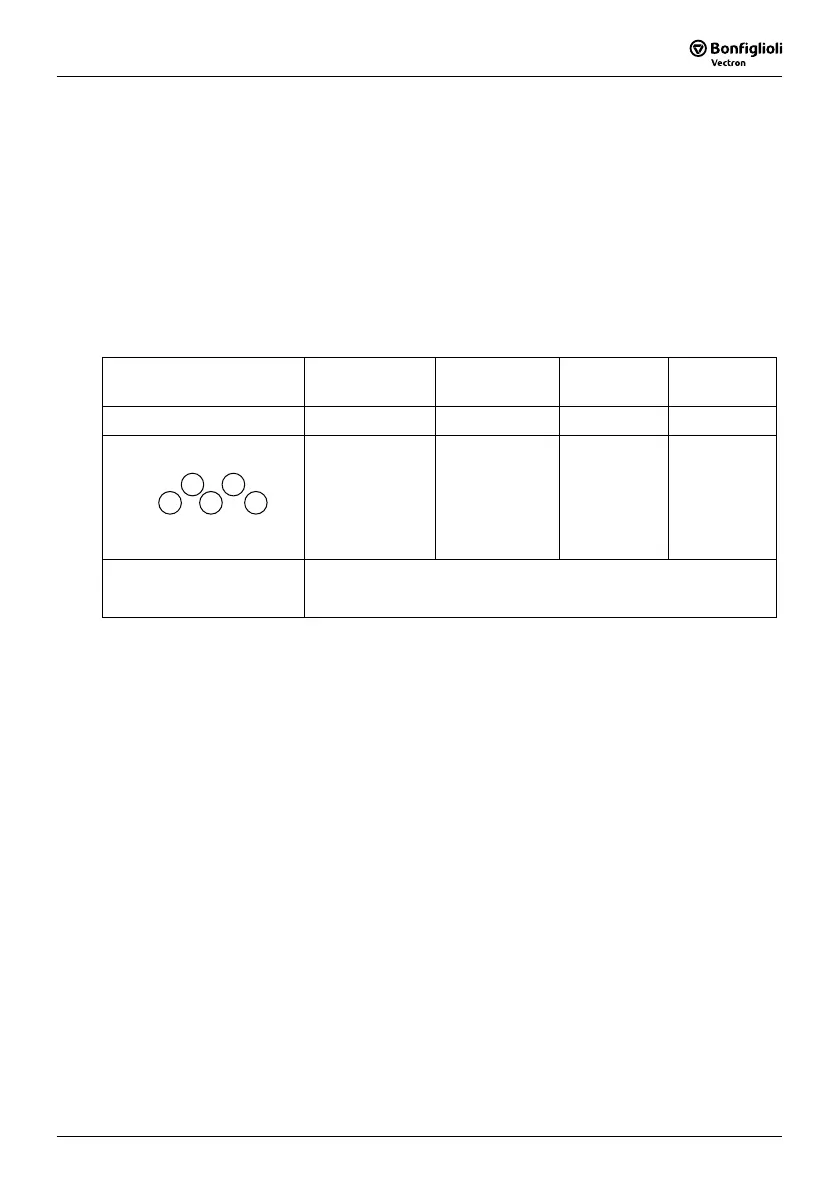
Suitable optional and Wiring Specification
Molded-Case Circuit Breaker / Magnetic Contact
z
Warrantee does not apply to damage caused by the following situations:
(1) Damage to the inverter caused by the lack of appropriate molded-case circuit breaker or
when a circuit breaker with too large of capacity is installed between the power supply
and the inverter.
(2) Damage to the inverter caused by the magnetic contact, phase advancing capacitor, or
surge-protector installed between the inverter and the motor.
Model Type SYN10 S 115 01/03
S 220 01/03 AF
S 115 05
S 220 05/07 AF
S 220 09 AF T 400
05/07/09 AF
Molded-case circuit breaker 15A 20A 30A 15A
Primary Circuit Terminal (TM1)
Wire dimension
(#14AWG) 2.0mm
2
Terminal screw M3
Wire dimension
(#14AWG)
2.0m m
2
Terminal screw
M3/M4
Wire dimension
3.5mm
2
Terminal screw
M4
Wire dimension
3.5mm
2
Terminal screw
M4
Signal Terminal (TM2)
1~11
Wire dimension 0.75mm
2
(#18 AWG), Terminal screw M3
Use copper conductors only size field wiring based on 80 degrees C wire only.
z
Please utilize three-phase squirrel-cage induction motor with appropriate capacity.
z
If the inverter is used to drive more than one motor, the total capacity must be smaller
than the capacity of the inverter. Additional thermal overload relays must be installed
in front of each motor. Use the Fn_18 at 1.0 times of the rated value specified on the
motor nameplate at 50Hz, 1.1 times of the rated value specified on the motor nameplate
at 60Hz.
z
Do not install phase advancing capacitors, LC, or RC component between the inverter
and the motor.
T3
T1
T2
L1 L2
 Loading...