Do you have a question about the BONFIGLIOLI Vectron Syn10 T400 05 AF and is the answer not in the manual?
| Category | Controller |
|---|---|
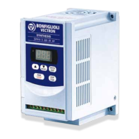
| Model | Vectron Syn10 T400 05 AF |
| Output current | 5 A |
| Frequency | 50/60 Hz |
| Power | 2.2 kW |
| Protection class | IP20 |
| Communication interface | Modbus RTU |
| Operating temperature | 0...+40 °C |
| Input voltage | 400V AC |
Safety precautions for handling the AC Drive, mentioning WARNING and CAUTION symbols.
Specific instructions and warnings related to operating the inverter.
Details the electrical and physical specifications of various inverter models.
Provides a visual representation of the inverter's wiring connections.
Details the functions of various terminals on the inverter.
Explains the functions of terminals in the control circuitry block.
Comprehensive list of inverter parameters, their functions, ranges, and settings.
Detailed explanation of specific parameter functions and their calculations.
Lists malfunctions that require manual intervention for resetting.
Details malfunctions that are operative and may auto-reset or require manual reset.
Outlines the schedule and methods for routine and periodical inverter checks.