38
F_18: Motor rated current = 0~200 %
1. The electronic thermal overload protection for motor
:
(1) Motor rated current = Inverter rated current x F_18
F_18 = Motor rated current / inverter rated current
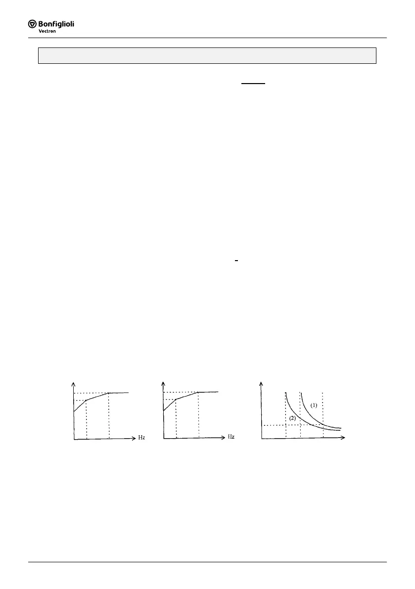
(2) When the load is within 100% of the motors rated current, the operation continues. When
the load reaches 150% of the motors rated current the operation is allowed to continue for
1 minute. (Refer to curve (1) in Figure 3)
(3) After protecting the motor with the electronic thermal switch activated, the inverter is cut off
immediately. The OLI light will flash. To resume operation, push the RESET button or
activate an external reset connection wired to terminal TM2.
(4) When the motor is operating at low speeds, the heat dissipation efficiency is lower. The
electronic thermal activation level is also reduced. (to change from curve (1) to curve (2) in
Figure 3. Choose the appropriate F_05 setting according to the applied motor to reach the
desired performance.
2. The electronic thermal protecting for inverter:
(1) When the load is within 103% of the inverters rated current, the operation
continues. When the load reaches 150% of rated current of the inverter, the
operation will continue for 1 minute. (Refer to curve (1) of figure 3)
(2) After the activation of the electronic thermal switch, the inverter is shut off immediately.
The OL2 light will flash. To resume the operation, push RESET button or activate an
external reset contact on terminal TM2.
F_05 = 1,2,3
50 Hz standard motors
%
F_05 = 4,5,6
60 Hz standard motors
100
90
60
100
90
60
Deca
20 50
(Figure 1)
20 60
100 150
(Figure 3)
In Percentage of Current
(Figure 2)
1.0
Decay
%
% of
current
 Loading...