EasyManuals Logo

BONFIGLIOLI Vectron Syn10 T400 05 AF User Manual

BONFIGLIOLI Vectron Syn10 T400 05 AF
58 pages
To Next Page IconTo Next Page
To Previous Page IconTo Previous Page
Page #20 background imageLoading...
Page #20 background image
16
16
(External 24V supply)
Primary Circuitry Terminal Block (TM1) descriptions
Terminal Symbol Function Description
L1 (R)
L2 (S)
L3 (T)
Primary power source input to Drive
Single phase: L1/L2
(for SYN10 S 115 01/03/05 and S 220 01/03/05) or L/N
Three phase: L1/L2/L3
P
R
External braking resistor terminal
(Only for models SYN 10 S 220 07/09 and T 400 05/07/09)
T1 (U)
T2 (V)
T3 (W)
Inverter output to Motor
Tightening torque for TM1 is 1 Nm (in the S 115 and S 220 01/03/05 models).
Tightening torque for TM1 is 1.3 Nm (in the S 220 07/09 and T 400 05/07/09 models).
* Wire voltage rating must be a minimum of 300V (200V series) and 600V (400V series)
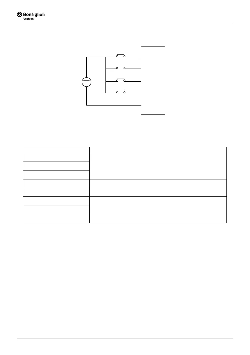
TM2
FWD
REV
SP1
RST
0V
3
4
6
7
10
+
24V
Inverter terminal descriptions

Table of Contents

Questions and Answers:

Question and Answer IconNeed help?

Do you have a question about the BONFIGLIOLI Vectron Syn10 T400 05 AF and is the answer not in the manual?

BONFIGLIOLI Vectron Syn10 T400 05 AF Specifications

General IconGeneral
CategoryController
ModelVectron Syn10 T400 05 AF
Output current5 A
Frequency50/60 Hz
Power2.2 kW
Protection classIP20
Communication interfaceModbus RTU
Operating temperature0...+40 °C
Input voltage400V AC

Related product manuals