39
F_19: Multifunctional input terminal 1 function = 1~ 6
F_20: Multifunctional input terminal 2 function = 1~ 6
1. F_19=1 or F_20 =1: JOG control (refer to F_09)
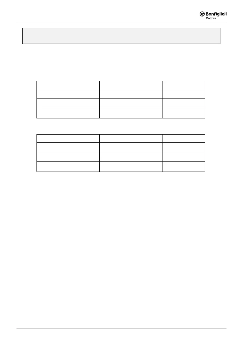
2. F_19, F_20 =2 or 6 Multi-speed control:
F_19=2 & F_20=6:
TM2 SP1 Terminal TM2 RESET Terminal Output frequency
ON OFF F_08
OFF ON F_26
ON ON F_27
F_19=6 & F_20=2:
TM2 SP1 Terminal TM2 RESET Te
r
minal Output frequency
ON OFF F_26
OFF ON F_08
ON ON F_27
3. F_19, F_20 =3: External quick stop
When the external quick stop signal is activated, the inverter proceeds to decelerate (by decele-
ration time set on F_02) and stop, (ignoring the setting of F_14). The inverters E.S. light will
flash after stopping. After the quick stop signal is deactivated, turn the RUN switch OFF and then
ON again to cycle it. (F_10 =1) Or, push the RUN key (F_10=0). The inverter will then resume
operation and restart. If the quick stop signal is removed before the inverter stops, the inverter
will still execute the quick stop. If an allarm will occur, the motor will coast to a stop.
4. F_19, F_20 =4: External Base Block (Immediate Shut Down)
When the external base block signal is activated, the inverter output will be immediately shut off
(ignoring the setting of F_14) and flash b.b. Light. After the base block signal is deactivated,
turn the RUN switch OFF and then ON again (F_10 = 1) or push the RUN key (F_10=0), the
inverter will restart from the original starting frequency.
 Loading...