(6) Wiring Method for the Feed Water Pump and the Oil Pump
(Feed Water Pump) (Oil Pump)
R S T R S T R S T R S T
| | | | | | | | | | | |
① ② ③ ① ② ③ Blue White Red Blue White Red
| | | | | |
⑥- ④ -⑤ ⑥ ④ ⑤ Yellow - Black - Green Yellow Black Green
(380V) (220V) (380V) (220V)
Note:
Rotating direction is to be checked after completion of wiring for the feed water pump and the oil pump.
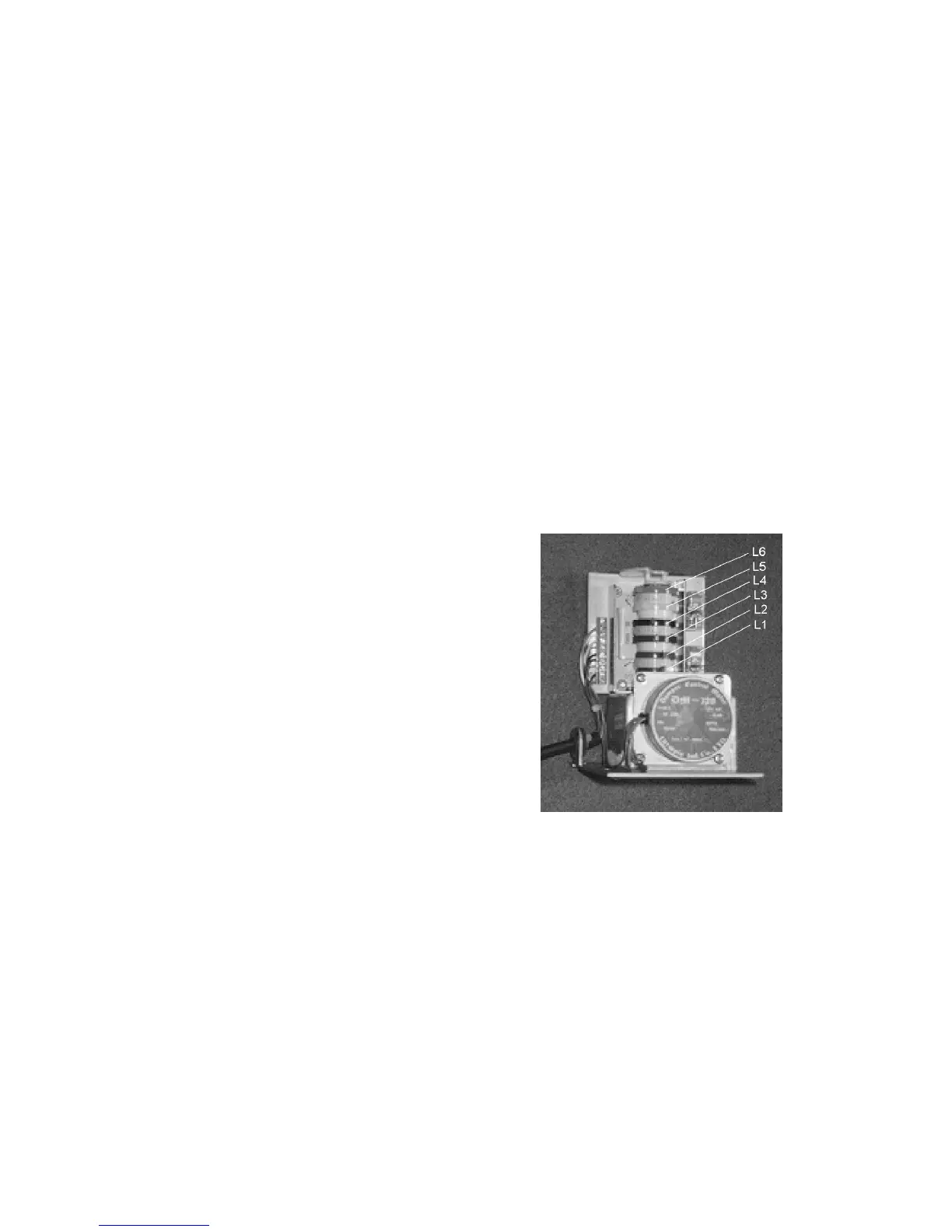
(7) Adjusting Method for the capacity(Damper Blade)
* TYPE : DM-320-3
1) Cam Adjusting Method for Control Position
① BLUE (L1) : Adjusting cam for “low over run” prevention.
② BROWN(L2) : Complete close position adjusting cam
③ GREEN (L3) : Position adjusting cam for 1st. solenoid valve
open and opening angle(Low fire angle position adjusting).
④ BLACK (L4) : Position adjusting cam for 1st. return(Returning
position adjusting from high fire to low fire).
⑤ YELLOW (L5) : Adjusting cam for 2nd. solenoid open position
(Position adjusting for 2nd solenoid valve opening movement).
⑥ RED (L6) : Position adjusting cam for 2nd. opening angle
(High fire opening angle position adjusting).
2) The Wire Colors of the Damper Motor
① Blue(S0), ②Green(R0), ③Black(OV1 In), ④Red(OV2 In)
⑤ White(OV2 Out), ⑩ Yellow(OV1 Out)
3) Adjusting Method and Example of the Damper Blade Angle
1. Cam Adjusting Method for Control Position
The cam is adjusted in the angle of L1<L2<L3<L4<L5<L6 and the damper is opened wider rotated
it clockwise.
2. Adjusting Example:
If you want to adjust at the damper angle of (3.0) when 1st. combustion and (6.5) when 2nd.
combustion, adjust as follows: