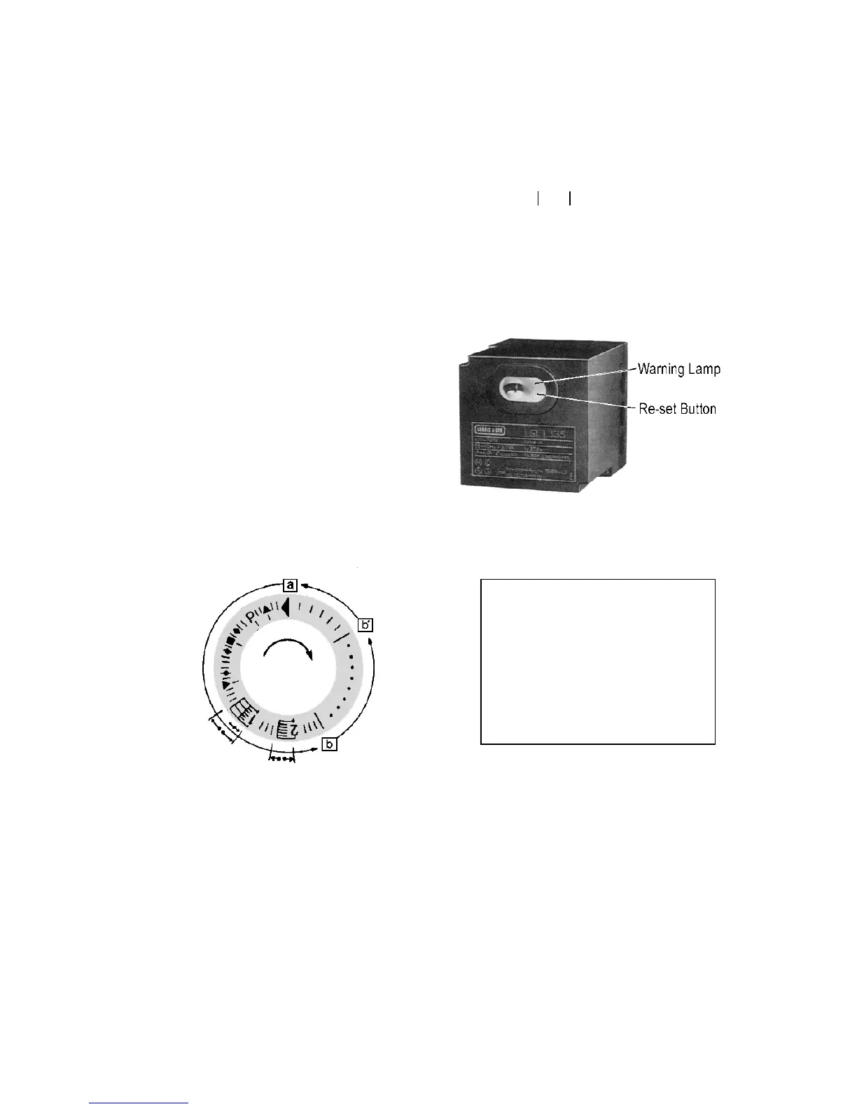
(10) Operation status for combustion Control(Protect Relay
◀ Ⅱ ▲ Ⅱ P ⅡⅡ ■ ⅡⅡⅡ ▼ ⅡⅡ ▤1 Ⅲ ▤2 Ⅲ …… ⅢⅢ ◀
Ⅰ Ⅰ Ⅰ Ⅰ Ⅰ Ⅰ Ⅰ Ⅰ Ⅰ Ⅰ Ⅰ
① ② ③ ④ ⑤ ⑥ ⑦ ⑧ ⑨ ①
( Combustion Control Sequence)
1) Ignition Program Indication Chart
① Manipulation start
② Damper open(Residual combustion gas exhaust)
③ Circuit check of the flame detector in the control
④ Damper close
⑤ Ignition transformer operation
⑥ 1st. combustion ignition
⑦ Ignition transformer operation stop
⑧ 2nd. combustion ignition
⑨ Normal operation
(Protect Relay: Combustion Controller)
[a] - [b] Ignition time
[b] - [b’] Normal combustion
[b’] - [a] Post purge
← • → Safe time in case of intermittent
pilot
← • • → Safe time in case of interrupted
pilot