Installation 33/52
RE 91071-01-B/03.2015, A2FM/A2FE Series 70, Bosch Rexroth AG
B
T
2
A
T
1
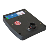
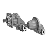
Fig. 10: Port overview A2FM, SAE flange ports on side
B
T
2
A
T
1
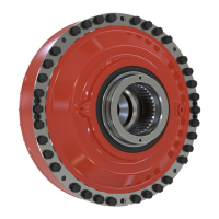
Fig. 11: Port overview A2FE, SAE flange ports on side
Table 10: Ports A2FM/A2FE Series 70
Ports
1)
p
max
[bar]
2)
Status
A2FMN/A2FEN A2FMM/A2FEM A2FMH/A2FEH
A, B Working port 350 450 500 O
T
1
Drain port 3 3 3 O
3)
T
2
Drain port 3 3 3 X
3)
1)
The measuring system and thread size can be taken from the installation drawing.
2)
Depending on the application, short-term pressure peaks can occur. Keep this in mind when
selecting measuring equipment and fittings.
3)
Depending on the installation position, T
1
or T
2
must be connected (see chapter7.3
“Installation position” on page26)
O = Must be connected (plugged on delivery)
X = Plugged (in normal operation)
Port overview
 Loading...