Bosch Security Systems, Inc.
130 Perinton Parkway
Fairport, NY 14450
USA
www.boschsecurity.com
Bosch Sicherheitssysteme GmbH
Robert-Bosch-Ring 5
85630 Grasbrunn
Germany
© 2018 Bosch Security Systems, Inc. F.01U.265.445 | 05 | 2018.05
Dimensions 4.5 in x 6.94 in x 1.15 in
(11.43 cm x 17.62 cm x 2.9 cm)
Output voltage (rated
range)
11.5 - 12.2 VDC (special
application)
AC line input voltage
frequency
120 VAC +10/-15% (60 Hz) 0.5 A
230 VAC +10/-15%(50Hz)250mA
Current available
(maximum)
2.0 A SDI2 Out and AUX Power
(combined)
(up to 4.0 A of alarm current for
Burglar Applications)
Current drawn from
the control panel
15 mA
Battery input 2 separate 12 V lead acid batter-
ies (7-18 Ah) 4.0 A max available
from charger.
Operating temperature +32°F to +120°F (0°C to +49°C)
Relative humidity 5% to 93% at +90°F (+32°C) non-
condensing
Storage temperature -4° to 140° F (-20° to 60°C)
Transformer power
supply
TR1850 - (18 VAC, 50 VA)
TR1850-CA - (18 VAC, 50 VA) for
Canada
DE-45-18 - (230/18VAC 45
VA) plug-in for Europe (P/N:
F01U166215)
Transformer wiring 12-18 AWG
Terminal wire size 12 AWG to 22 AWG
(2 mm to 0.6 mm)
Copyright
This document is the intellectual property of Bosch Security Systems, Inc. and is protected by copyright. All rights reserved.
Trademarks
All hardware and software product names used in this document are likely to be registered trademarks and must be treated accordingly.
Bosch Security Systems, Inc. product manufacturing dates
Use the serial number located on the product label and refer to the Bosch Security Systems, Inc. website at
http://www.boschsecurity.com/datecodes/.
SDI2 wiring *Maximum distance - Wire size:
(Unshielded wire only)
1000 ft (305 m) - 22 AWG (0.6
mm)
1000 ft (305 m) - 18 AWG (1 mm)
*Maximum wiring distance from the
panel to the last SDI2 module can
not exceed 1000 ft.
Compatibility B9512G/B9512G-E
B8512G/B8512G-E
B6512
B5512/B5512E
B4512/B4512E
B3512/B3512E
GV4 Series control panels
AE1/AE2 Enclosure
B10 Enclosure
D2203 Enclosure
BATB-40 Enclosure**
B8103/D8103 Enclosure**
D8108A Attack Enclosure**
**requires B12
Usage Intended for indoor/dry use
11 | Next
9 | Certifications
10 | Specifications
8 | Configuration
Region
USA UL 365 - Police Station Connected Burglar Alarm
Units and Systems
UL 609 - Local Burglar Alarm Units and Systems
UL 636 - Hold Up Alarm Units
UL 864 - Control Units and Accessories for Fire
Alarm Systems
UL 985 - Household Fire Warning System Units
UL 1023 - Household Burglar Alarm System
Units
UL 1076 - Proprietary Burglar Alarm Units and
Systems
UL 1610 - Central Station Burglar Alarm Units
CSFM - California State Fire Marshal
FCC Part 15 Class B
Europe CE - EMC Directive (EMC)
CE - Low-Voltage Directive (LVD)
El-gr: Μεταβείτε στη διεύθυνση https://gr.boschsecurity.com/el/ για την τεκμηρίωση
σε αυτήν τη γλώσσα.
Es-es: Visite https://es.boschsecurity.com/es/ para obtener documentación en este
idioma.
Fr-fr: Accédez à l’adresse https://fr.boschsecurity.com/fr/ pour obtenir la
documentation dans cette langue.
Hu-hu: A honosított dokumentációt lásd a https://hu.boschsecurity.com/hu/
oldalon.
It-it: Andare a https://it.boschsecurity.com/it/ per la documentazione in questa
lingua.
Pl-pl: Dokumentacja w tym języku znajduje się w witrynie https://pl.boschsecurity.
com/pl/
Pt-br: Acesse http://pt.boschsecurity.com/pt/ para obter a documentação neste
idioma.
Region
Canada CAN/ULC S303 - Local Burglar Alarm Units and
Systems
CAN/ULC S304 - Signal Receiving Centre and
Premise Alarm Control Units
CAN/ULC S545 - Residential Fire Warning Con-
trol System
ULC-ORD C1023 - Household Burglar Alarm
System Units
ULC-ORD C1076 - Propriety Burglar Alarm Unit
and Systems
ICES-003 - Digital Apparatus
7 | Troubleshooting
When the tamper switch is activated (closed to open), the
heartbeat LED stays OFF for 3 seconds, then shows the
firmware version. The LED pulses the major, minor, and
micro digits of the version, with a 1 second pause after each
digit.
Flashing patterns start after the tamper is open (short is
removed). The following is an example: The version 1.4.3
would be shown as LED flashes:
[3 second pause] *___****___*** [3 second pause, then
normal operation]
• With a tamper switch, push and release the switch with
the enclosure door open.
• Without a tamper switch, briefly short the tamper pins.
Refer to the following illustration for an example of flash
pattern
s.
6 | Show the firmware version
Flash pattern Corrective action
Heartbeat – 3 quick
flashes every 1 sec
1. Check wiring connection.
2. Check Control panel
programming.
3. Check address selections.
BATT 1 (BATT 2) – 3
quick flashes every
1 sec
1. Measure the voltage at the
terminals.
2. If the voltage is above 13.3
VDC, and the battery is a fully
charged, the module goes back
to normal state after some of
the energy is removed from the
battery.
3. If the voltage is below 13.3 VDC,
the module may be damaged.
AC Flashing Measure the AC voltage before
and after the transformer. If there
is voltage before and none after,
replace the transformer.
Use Remote Programming Software to program the control
panel to work with the module. For programming parameter
descriptions, options, and defaults using RPS, refer to RPS Help.
en Installation Guide
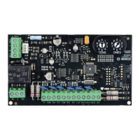
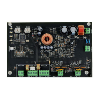
Auxiliary Power Supply Module
B520
 Loading...