Do you have a question about the Bosch B520 and is the answer not in the manual?
Explains how to set the address switches on the module for system communication using a screwdriver.
Steps to install the module using mounting clips and screws in specific enclosures.
Procedure for attaching the grounding wire lug to the bolt and door hinge.
Instructions for attaching the module to a mounting plate using screws.
Steps for attaching the module to an enclosure that mounts to a B12 mounting plate.
Procedure for mounting the B12 plate into the B8103 enclosure using tabs and screws.
Guidance on connecting the system to earth ground using appropriate wire and grounding devices.
Steps for attaching Battery 1 and Battery 2 to the module, ensuring correct capacity.
Guidance on selecting battery sizes for commercial fire and burglar applications based on current draw.
Corrective actions for specific LED flash patterns like Heartbeat and BATT 1/2.
Steps to diagnose AC LED issues, including voltage measurement and transformer checks.
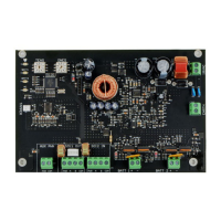
The B520 Auxiliary Power Supply Module is designed to provide additional 12 VDC power for Fire and Burglar standby power applications, supplying a maximum of 2A. This module is compatible with various Bosch control panels and enclosures, offering flexibility in installation and system integration.
The B520 module serves as an auxiliary power supply, augmenting the power capabilities of a security system. It supports both Fire and Burglar standby power requirements, ensuring continuous operation of critical components during power outages. The module integrates with the control panel via the SDI2 bus, allowing for communication and power distribution to other SDI2 devices. It accepts a 18 VAC transformer input and can connect to one or two 12 V lead-acid batteries (7 Ah or 18 Ah) for backup power. The module's design includes terminals for auxiliary power output, a tamper switch connector, and an earth ground connection for enhanced safety and system integrity.
Installation: The module can be installed in various enclosures, including B10, D2203, AE1, AE2, B8103, and BATB-40. For B10, D2203, AE1, and AE2 enclosures, the module is secured using mounting clips and screws. A grounding wire is attached to the enclosure bolt and door hinge to ensure proper grounding. For the B8103 enclosure, the module attaches to a B12 mounting plate, which is then mounted within the enclosure using skirt hooks and a screw. It is crucial to remove all power (AC and battery) before making any connections to prevent injury or equipment damage. The module should be connected to earth ground before making other connections to prevent damage from electrostatic charges or transient electrical surges.
SDI2 Address Settings: The module uses address switches for communication with the control panel. These settings are configured via the control panel. Each module in a system must have a unique address. The module reads the address switch setting only during power-up, requiring a power cycle for any new settings to take effect. For single-digit addresses (1-9), the tens switch should be set to 'O' and the ones switch to the appropriate number.
Wiring: The module connects to the control panel using the SDI2 IN terminal strip (PWR, A, B, and COM). It also provides SDI2 OUT terminals and interconnect wiring connectors for connecting to other powered SDI2 devices. For non-SDI2 devices, the AUX PWR terminal strip (PWR and COM) is used. Battery connections are made to BATT 1 and BATT 2 terminals, ensuring that if two batteries are used, they have the same capacity rating. The plug-in transformer connects to the 18 VAC B520 terminal. It is important to keep 0.25 inches (6.4 mm) space between power-limited and non-power-limited wiring.
Battery Configurations: The module supports various battery configurations based on the enclosure type and desired standby hours. For commercial fire applications, battery size is determined by current calculations against required standby hours. For burglar applications, similar calculations are performed. If the current load exceeds the capacity of a single B520, a second B520 can be used to split the load.
LED Indicators: The module features on-board LEDs for troubleshooting and status monitoring:
Firmware Version Display: The firmware version can be displayed by briefly activating the tamper switch (push and release with the enclosure door open, or briefly short the tamper pins if no switch is present). The heartbeat LED will turn off for 3 seconds, then pulse to show the major, minor, and micro digits of the version, with a 1-second pause between each digit. For example, version 1.4.3 would be shown as one flash, then a pause, then four flashes, then a pause, then three flashes.
Configuration: The module can be programmed using Remote Programming Software (RPS) to integrate with the control panel. RPS Help provides detailed information on programming parameters, options, and defaults.
| Model | B520 |
|---|---|
| Type | Control Unit |
| Operating Voltage | 12 VDC |
| No. of On-Board Zones | 8 |
| Max Zones | 8 |