1 689 975 288 2017-06-30| Robert Bosch GmbH
Overview | BAT 690 | 21 en
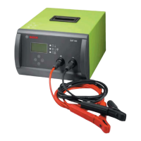
3. Overview
3.1 BAT 690
4510027-08_Ko
1
2
3
4
5
7
8
9
Fig. 1: Overview
1 On/Off switch
2 Mains port
3 Connection for red (+)/black (–) charging cable
4 USB port
5 Selection keys
6 TFT display
7 Red LED for "Mains on", "Incorrect polarity", "Fault or overload"
8 Green LED for "charging operation"
9 Yellow LED for "Back-up mode" and "Buffer mode"
3.1.1 Top part of housing
1
2
4510027-14_shd
Fig. 2: Top part of housing
1 Circuit board M1 (HMI)
2 USB circuit board
3.1.2 Lower housing part
1
2
3
4510027-13_shd
4
5
6
Fig. 3: Lower housing part
1 Power module 1 (Slave 0)
2 Fan 1
3 Power module 2 (Slave 1)
4 Fan 2
5 Shielding plate
6 Power connector with on/off switch (power inlet socket
connector)
 Loading...