1 689 975 288 2017-06-30| Robert Bosch GmbH
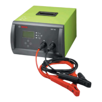
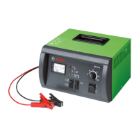
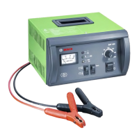
Faults & Troubleshooting | BAT 690 | 27 en
5. Faults & Troubleshooting
DANGER - Risk of electric shock from live
parts!
¶ Work on electrical systems or equipment
must only be performed by qualified
electricians or trained personnel under
the guidance and supervision of an
electrician.
¶ Observe the electrical engineering safety
regulations.
5.1 General view of all faults
Symptom / fault message Remedy
on page
Nothing displayed after being switched on 27
"No battery connected" 28
"Warning! Checking clips" 28
"Warning! Overvoltage" 28
"Fault! Call customer service" 28
"Fault no.: 10" 28
"Fault no.: 20" 28
"Fault no.: 30" 29
"Fault no.: 40" 29
"Fault no.: 100" 29
"Fault no.: 110" 29
"Fault no.: 120" 29
"Fault no.: 130" 29
"Fault no.: 140" 29
"Fault no.: 200" 30
"Fault no.: 210" 30
"Fault no.: 220" 30
"Fault no.: 230" 30
"Fault no.: 290" 30
"Fault no.: 300" 31
"Fault no.: 310" 31
"Fault no.: 320" 31
"Fault no.: 330" 31
"Fault no.: 340" 32
"Fault no.: 350" 32
"Fault no.: 360" 32
"Fault no.: 370" 32
"Fault no.: 390" 33
5.2 Faults in initialization mode
Nothing displayed after being switched on
Possible cause:
R Power supply cable with open circuit
R Connection between circuit board M1 and power
module is interrupted
R Device fuse is defective
R Auxiliary voltage is defective
R Circuit board M1 is defective
Remedy:
1. Check the power supply unit for continuity.
2. Replace the power supply cable if there is a
malfunction.
DANGER – Risk of electric shock from live
parts. Observe the electrical engineering safety
regulations.
3. Establish and secure connection between circuit
board M1 and power module 1 (see sec. 6).
4. Check mains voltage at power module 1 and power
module 2 at measuring points M1 and M2 (see sec.
5.6).
Mains voltage must be 230V.
Device fuse is defective if mains voltage differs.
5. Replace corresponding power module if mains
voltage differs.
6. Check auxiliary voltage at power module 1 and
power module 2 at measuring points IC 14 Pin 1 and
GND1 Pin 4 (see sec. 5.6).
Auxiliary voltage must be 12V.
7. Replace corresponding power module if auxiliary
voltage differs.
8. Connect customer service circuit board M1 to power
module 1 and BAT 690 check function.
If BAT 690 functions with the customer service
circuit board M1, the M1 circuit board of the cus-
tomer is defective.
9. Replace the customer's M1 circuit board.
10. Define power module 1 with jumper setting as Slave
1 (see sec. 4.4.4).
11. Connect power module 2 to circuit board M1 and
BAT 690 check function.
If BAT 690 functions, power module 1 is defec-
tive.
If BAT 690 does not function, power module 1
and power module 2 are defective.
12. Replace power module 1 and/or power module 2.
 Loading...