9
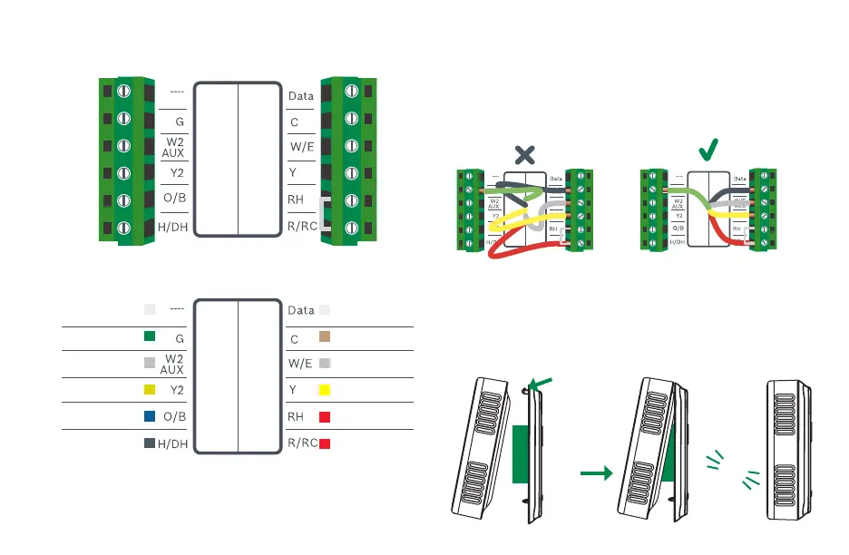
R/RC
BCC110 Terminal
After all wires are securely connected,
gently push any excess wires back into
the hole in the wall
Step 10
Attach the BCC110 thermostat to
the BCC110 wall plate
Step 11
PUSH
HOOK
CLICK
BCC110 Terminal Key
Alarm Input
3
C-wire (common)
1st Stage Heating
1
1st Stage Compressor
Heating Appliance Power
Thermostat Power/
Cooling Appliance Power
Not Used
Fan
(W2) 2nd Stage Heating
2
2nd Stage Compressor
2nd Stage Heating
Humidifier/Dehumidifier
Reversing Valve
Note: The color of your wires may not be the same as shown
(1)Emergency Heat activated at W/E,
(2)Single-stage Auxiliary heat activated at W2/AUX,
(3)Only to be used with Bosch WSHP