Product information
BH 120-300-5 – 6 720 821 243 (2022/06)
23
2 Product information
2.1 Correct use
Buffer cylinders may only be filled with heating water.
Only use buffer cylinders in sealed heating systems.
Operate the buffer cylinders BH 120-5, BH200-5, BH 300-5 preferably
in combination with heat pumps.
Any other use is considered incorrect. Any damage that may result is
excluded from liability.
2.2 Scope of Delivery
• Buffer cylinder
• Installation and servicing instructions
2.3 Technical data
• Dimensions and specifications ( Fig. 1, page 54)
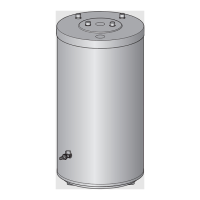
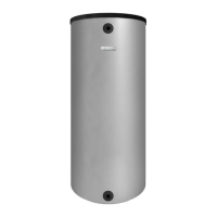
2.4 Product description
2.5 Data plate
The data plate is located at the top of the rear of the buffer cylinder and
includes the following details:
2.6 Product datasheet on energy consumption
The following product data complies with the requirements of EU Regulation No 814/2013 as a supplement to Ecodesign Directive 2017/1369/EU and
Regulations EU 814/2013 as retained into UK law and amended..
Unit BH 120-5
A
BH 200-5
A
Available capacity (total) l 120 203
Standby heat loss
1)
1) EN 12897; Excluding distribution losses outside the buffer cylinder.
kWh/24h 0,9 1,0
Maximum heating water
temperature
°C 90 90
Maximum heating water
operating pressure
bar
(positive)
3 3
Table 2 Technical data (A)
Unit BH 120-5
B
BH 200-5
B
BH 300-5
B
Available capacity (total) l 120 203 307
Standby heat loss
1)
1) EN 12897; Excluding distribution losses outside the buffer cylinder.
kWh/24h 1,1 1,4 1,8
Maximum heating water
temperature
°C 90 90 90
Maximum heating water
operating pressure
bar
(positive)
3 3 3
Table 3 Technical data (B)
Item Description
1 Heating system flow
2 Casing, painted sheet metal with rigid polyurethane foam
insulation
3 Heating system return
4 Return to heat pump
5 Sensor well for return temperature sensor (GT1)
(Test point)
6 Drain tap
7 Storage cylinder, steel
8 Flow from heat pump
9 Plug with sensor well for flow temperature sensor (T1)
10 Air vent valve
11 PS casing lid
Table 4 Product description (
Fig. 2, page 55)
Item Description
1 Type
2 Serial number
3 Available capacity (total)
4 Standby heat loss
6 Year of manufacture
9 Max. heating water flow temperature
17 Max. heating water operating pressure
Table 5 Data plate
Product number Product typ Storage volume (V) Standing loss (S) Water heating energy efficiency class
7 735 501 535 BH 120-5 1 120,0 l 35,2 W A
7 735 500 777
8 718 543 039
BH 120-5
BST 120-5 Ehp
122,9 l 46,8 W B
7 735 501 538 BH 200-5 1 203,7 l 41,4 W A
7 735 500 778
8 718 543 047
BH 200-5
BST 200-5 Ehp
203,6 l 58,2 W B
7 735 500 795
8 718 542 850
BH 300-5
BST 300-5 Ehp
307,2 l 74,2 W C
Table 6 Product datasheet on energy consumption
 Loading...