BH 120-300-5 – 6 720 821 243 (2022/06)
24
Regulations
3Regulations
Observe the following directives and standards:
• Local regulations
• EnEG (in Germany)
• EnEV (in Germany)
Installation of, and equipment for, heating and water heating systems:
• DIN and EN standards
– DIN 4753, part 1: DHW cylinders and DHW heating systems for
potable and process water; requirements, identification,
equipment and testing
– DIN 4753, part 8: Thermal insulation of DHW cylinders up to
1000 l nominal capacity – requirements and testing (product
standard)
– DIN EN 12 828: Heating systems in buildings - engineering hot
water heating systems
– DIN 18 380: VOB
1)
, heating systems and central DHW systems
– DIN 18 381: VOB1), gas, water and sewage installation work
within buildings
–VDE regulations.
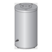
4Transport
▶ Secure the buffer cylinder to prevent it falling during transport.
▶ Transport the tank ( Fig. 3, page 55).
5Fitting
▶ Check that the buffer cylinder is complete and undamaged.
5.1 Installation location
▶ Site the buffer cylinder on a plinth if there is a risk that water may
collect at the installation site.
▶ Site the buffer cylinder in dry internal areas that are free from the risk
of frost.
Only with BH 200-5, BH 300-5:
▶ Observe the minimum wall clearances inside the installation room
( Fig. 5, page 56).
5.2 Installing the buffer cylinder
▶ Stand the buffer cylinder upright and level it ( Fig. 6 to Fig. 7,
page 56).
▶ Remove the protective caps.
▶ Apply Teflon tape or Teflon string ( Fig. 8, page 56).
5.3 Hydraulic connection
▶ When sizing the heating system expansion vessel, take the cylinder
capacity into consideration.
▶ Install pipework runs so that natural circulation is prevented.
▶ Install all pipes free of stress.
▶ During filling, open the ventilation on the cylinder ( Fig. 2, [10],
page 55).
The test pressure must not exceed 3 bar positive pressure.
▶ Carry out tightness test ( Fig. 16, page 58).
System components
Function diagram for connecting the buffer cylinder to the heat pump
( Fig. 9, page 57).
5.4 Installing temperature sensors
▶ Fit the temperature sensors ( Fig. 10 and 11, page 57).
▶ Note sensor positions ( Fig. 2, [5] and [9], page 55).
▶ Observe heat pump or control unit installation instructions.
6 Commissioning
▶ Commission all assemblies and accessories as specified in the
manufacturer's technical documentation.
Instructing users
▶ Explain the operation and handling of the heating system and buffer
cylinder, making a particular point of safety-relevant features.
▶ Explain the function and checking of the safety valve.
▶ Hand all enclosed documents over to the owner/operator.
▶ Highlight the following for the user:
1) VOB: German contract construction procedures – Part C: General technical
specifications in construction contracts (ATV)
NOTICE: System damage through inadequate load
bearing capacity of the supporting surface or unsuitable
substrate.
▶ Ensure that the installation area is level and offers
sufficient load-bearing capacity.
DANGER: Risk of fire from soldering and welding.
▶ Take appropriate protective measures when
soldering and welding as the thermal insulation is
combustible (for example, cover the thermal
insulation).
CAUTION: Water damage resulting from open drain
(only BH 200-5, BH 300-5)!
▶ Connect the drain to the bottom cylinder connection
( Fig. 2, [3], page 55) prior to filling the cylinder.
CAUTION: Risk of damage to non heat-resistant
installation materials (e. g. plastic piping)!
▶ Use installation material which is heat resistant to
80 °C.
Only fill buffer cylinders with potable water.
Item Description
1 Heat pump
2 Heating system
3 Additional heating system (in case of expansion)
4 Pump
5 3-way mixer
6 Buffer cylinder
Table 7 System components (
Fig. 9, page 57)
Ensure that the sensor area has contact with the sensor
pocket area for the sensor‘s full length.
NOTICE: Cylinder damage resulting from positive
pressure!
▶ Never close the blow-off line of the safety relief valve.
 Loading...