en 15BSL 2470
Robert Bosch GmbH 1 689 979 848 (2005-06-14)
2.3 Device description
B
OS
CH
2
4
V
DC
AMPERE
S
0
4
0
8
0
1
0
0
1
2V
B
S
L
2
4
7
0
B
OS
CH
A
60
2
0
2
3
1
45
100011/1P
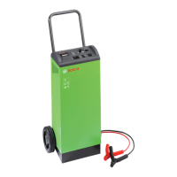
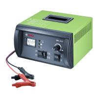
Fig. 1: BSL 2470
1 Charger cable with crocodile clip-on terminals
2 Curved handle
3 Running wheel
..2. Product description
B
OS
CH
24V
DC
AM
PERES
0
30
12V
B
SL
2470
A
60
90
45100011/2P
1
2
3
4
5
6
7
8
9
10
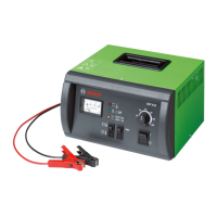
Fig. 2: BSL 2470 control and display elements
1 Battery charge current display instrument
2 Red LED for „Mains ON“ (permanently on) and
„Reverse-polarity or excess externally-supplied vol-
tage at battery crocodile clip-on terminals“ (LED
flashes)
3 Green LED for „Maximum charge voltage reached“
(continuous light)
4 Yellow LED for „Charging underway“ (continuous
light)
5 Two-way switch for battery nominal voltages 12 V
and 24 V
6 Two-way switch for battery temperature
7 Battery under-voltage button
8 Potentiometer for adjusting the charge and start-
assist currents
9 Mains switch
10 Device fuses
 Loading...